
Image forming apparatus and method of controlling the image forming apparatus

a technology of image forming apparatus and image forming apparatus, which is applied in the direction of digital output to print units, instruments, visual presentations, etc., can solve the problems of poor density correction and unreflectiveness, and achieve the effect of sacrificing accuracy

Inactive Publication Date: 2014-10-30
OKI DATA CORP
View PDF5 Cites 8 Cited by
  • Summary
  • Abstract
  • Description
  • Claims
  • Application Information

AI Technical Summary

Benefits of technology

This patent is about an image forming apparatus and method that can correct density without sacrificing accuracy, even if certain areas on the belt have different reflections. The apparatus has a density detection section that forms a density detection image on the belt and a light source that irradiates it with light. A light receiving section receives the reflected light and outputs an intensity signal. A selecting section selects a number of levels of light intensity, and a density correcting section uses these levels to perform density correction for the image forming unit. The technical effect of this patent is to improve the accuracy of image density correction even when certain areas on the belt have different reflections.

Problems solved by technology

The reflection characteristic of the joined portion may differ from that of the other portions of the belt, causing uneven reflection compared to other areas of the belt.
Therefore, conventional printers suffer from a problem in that the light reflected from the jointed portion of the belt causes poor density correction results.

Method used


Image

  • Image forming apparatus and method of controlling the image forming apparatus
  • Image forming apparatus and method of controlling the image forming apparatus
  • Image forming apparatus and method of controlling the image forming apparatus

Examples


embodiment

[0043]With reference to the drawings, a description will be given of an image forming apparatus and a method of controlling the image forming apparatus. The image forming apparatus will be described with respect to a printer.

{Configuration}

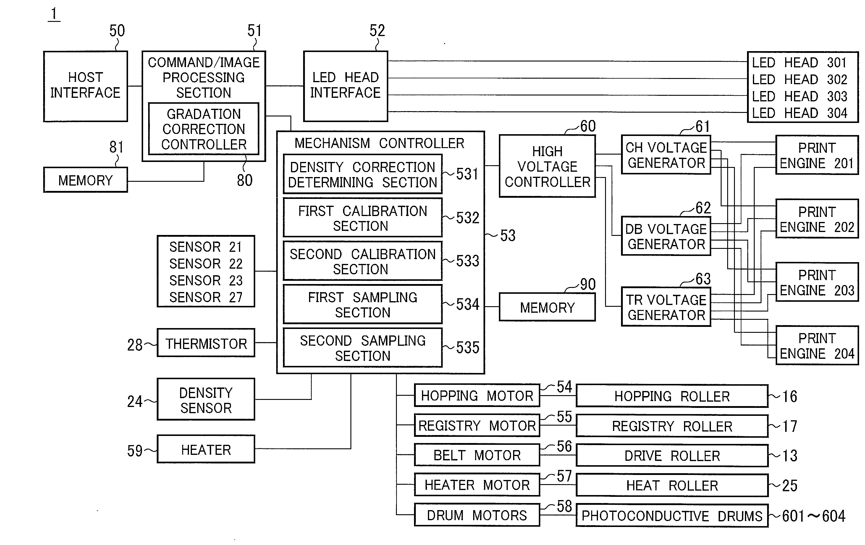
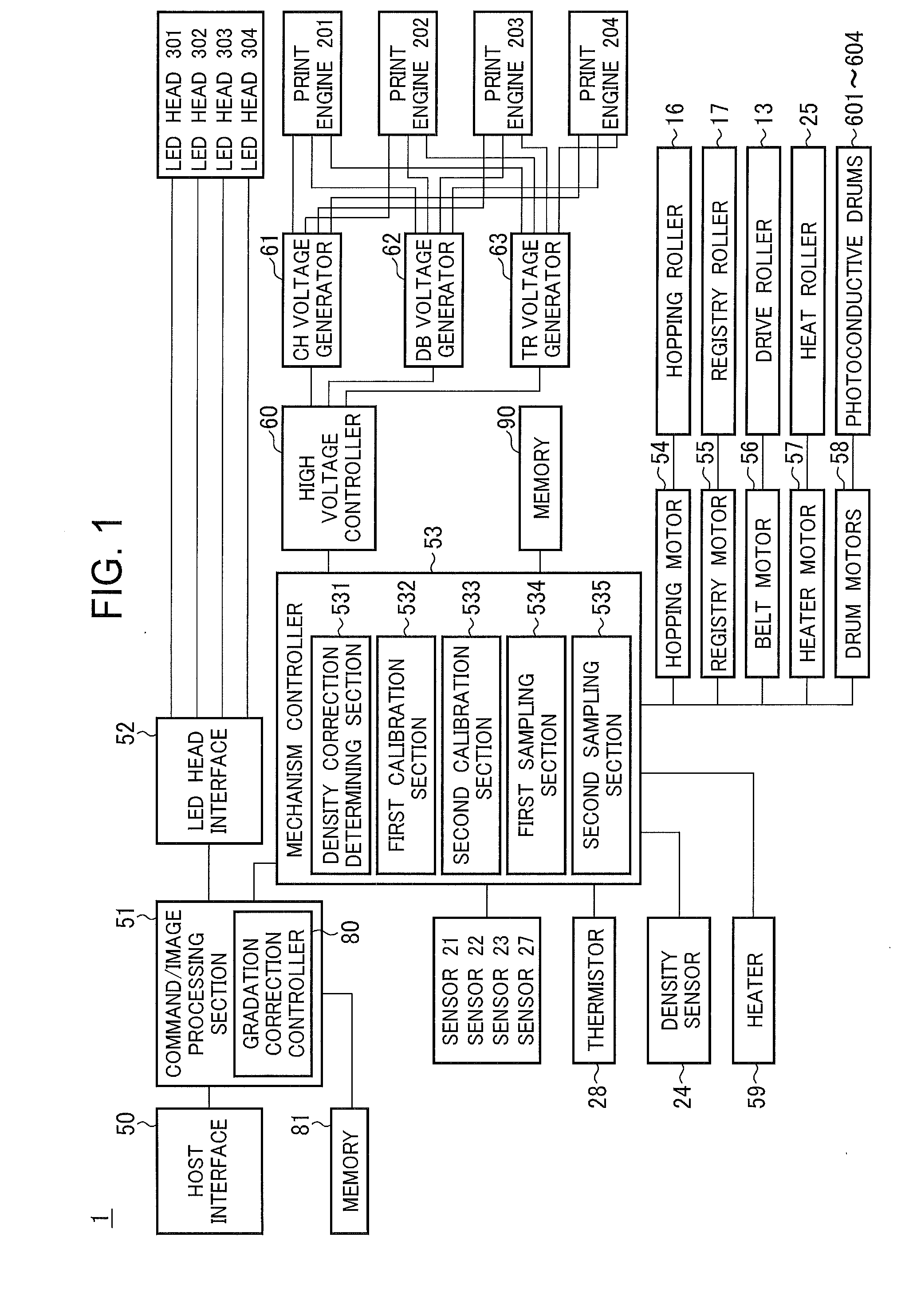
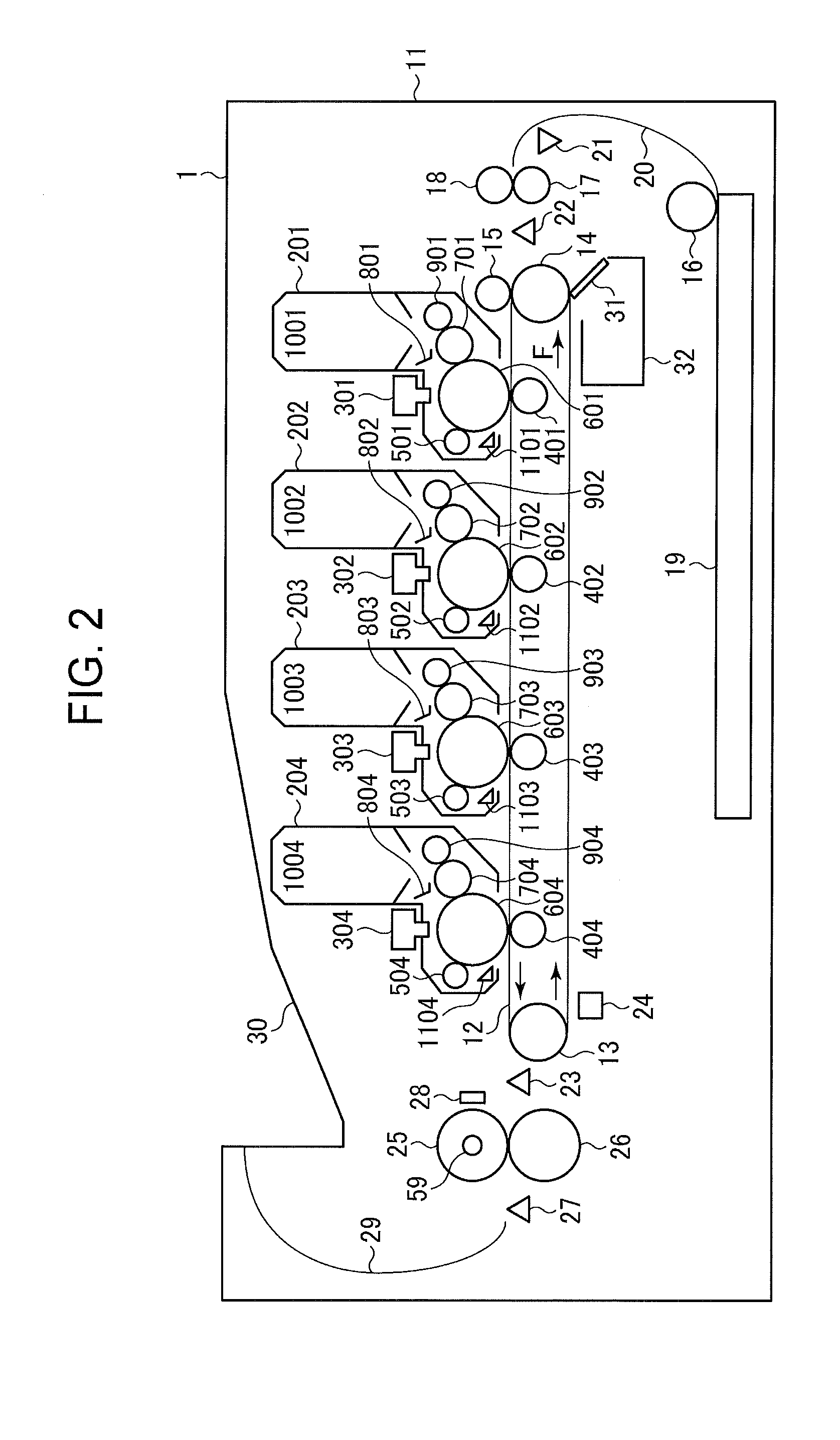
[0044]An image forming apparatus 1 takes the form of an electrophotographic printer with LED exposing devices. FIG. 1 is a block diagram illustrating the control system of the image forming apparatus 1. FIG. 2 is a schematic cross-sectional view of the image forming apparatus 1.

[0045]Referring to FIG. 2, the image forming apparatus 1 includes four independent process units or print engines 201, 202, 203, and 204 for forming black (K), yellow (Y), magenta (M) and cyan (C) images, respectively. A transport belt 12 extends from the black print engine to a fixing unit and serves as a part of a transport path in which a print medium such as paper is transported. The print engines 201, 202, 203, and 204 are aligned in this order along the transport belt...


PUM


Abstract

An image forming apparatus performs density correction. An image forming section forms a density detection image on a belt. A light source irradiates the image with light. A light receiving section receives light reflected from the image and outputs a plurality of intensity signals of the received light. An intensity obtaining section drives the belt and the light source, thereby illuminating the image a first number of times at intervals of a first distance as the belt runs, and the light receiving section receives the light reflected from the image, the first number of times being determined by at least the first distance and a second distance in which the first distance lies. A selecting section selects a second number of levels of light intensity from the plurality of intensity signals. A density correcting section performs print density correction using the second number of levels of light intensity.

Description

BACKGROUND OF THE INVENTION[0001]1. Field of the Invention[0002]The present invention relates to an image forming apparatus and a method of controlling the image forming apparatus, and more particularly to an electrophotographic printer with a density detecting mechanism for correcting the print density of an image.[0003]2. Description of the Related Art[0004]Conventional color image forming apparatus, including a color electrophotographic printer, include a plurality of so-called process units, each process unit including a photoconductor, charging means, exposing means, and developing means. A tandem color image forming apparatus includes four process units: black (K), yellow (Y), magenta (M), and cyan (C) process units aligned along a paper transport path. When paper advances through these process units, toner images of corresponding colors are transferred one over the other onto the paper in registration.[0005]In the aforementioned image forming apparatus, the print density of i...

Claims


Application Information

Patent Timeline
IPC IPC(8): G06K15/14
CPCG06K15/14H04N2201/04744H04N2201/04731H04N2201/04732H04N2201/0471H04N2201/04767H04N2201/04734H04N2201/04729H04N2201/04712G06K15/027H04N1/6033H04N1/6044
Inventor KATO, HIROSHI
Owner OKI DATA CORP
Learn More