Fluid analyzer and associated methods

a fluid analyzer and analyzer technology, applied in the field of equipment and methods of treatment, can solve the problems of strain gauges in particular being easily damaged, affecting the accuracy of the results, and increasing the cost of each

Inactive Publication Date: 2014-10-30
ATRIUM MEDICAL
View PDF6 Cites 79 Cited by
  • Summary
  • Abstract
  • Description
  • Claims
  • Application Information

AI Technical Summary

Problems solved by technology

There are various means to measure the fluid in the sealed container and each is associated with a cost, either in clinician time in making an observation or measurement, or in equipment cost in providing sensors and signaling devices for making a measurement and bringing the measurement data to the attention of the clinician or a hospital information system.
As the accuracy of the strain gauge increases, the gauge becomes more expensive and more susceptible to damage.
Strain gauges in particular are easily damaged, and if designed to be more robust have less resolution to weight change.
Clinical staff monitoring of a patient on a CDU, required to record fluid drainage volume levels of a patient, is awkward, time consuming and, therefore, costly and not measured or checked as often as otherwise might be desirable.

Method used


Image

  • Fluid analyzer and associated methods
  • Fluid analyzer and associated methods
  • Fluid analyzer and associated methods

Examples


Embodiment Construction

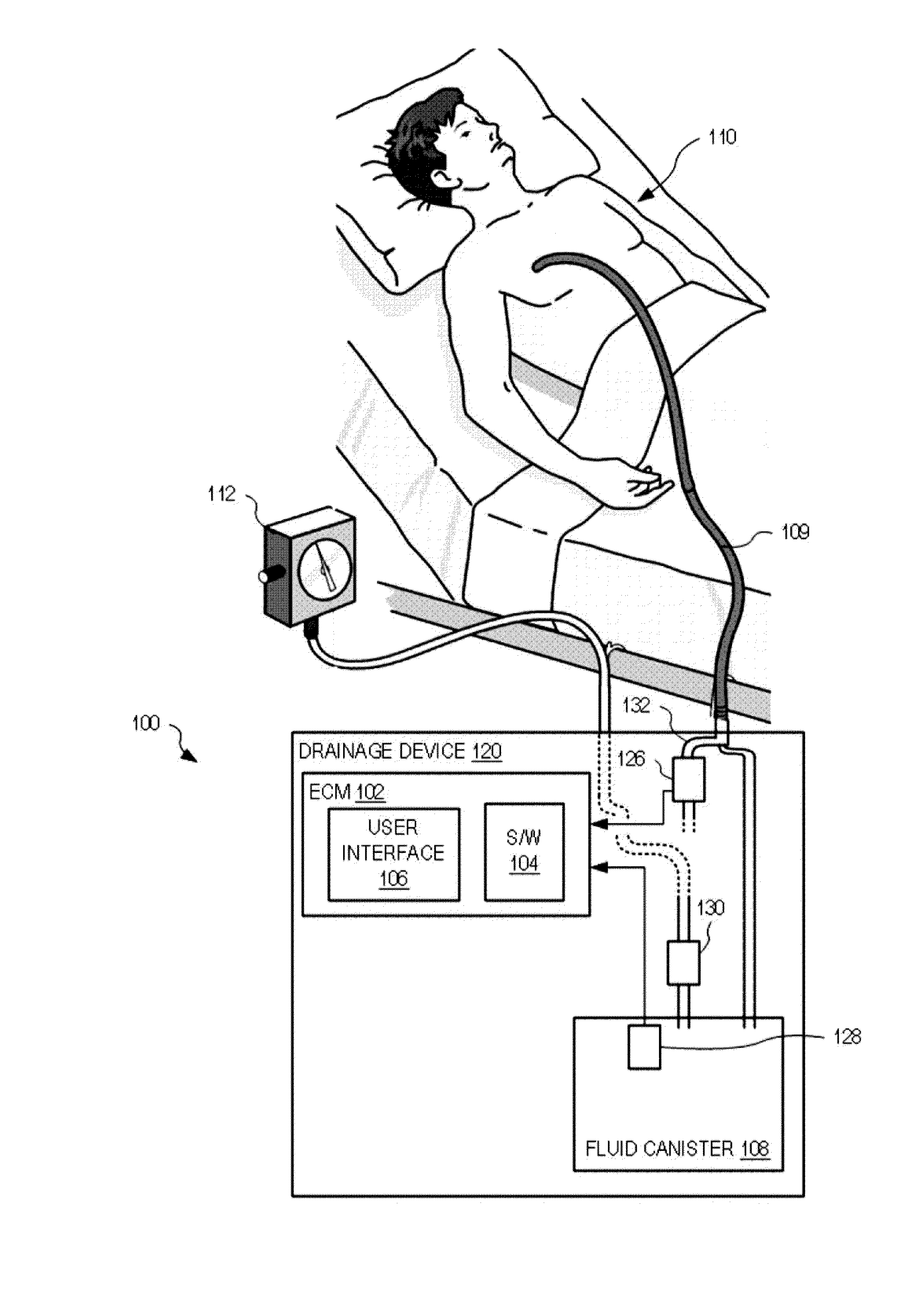
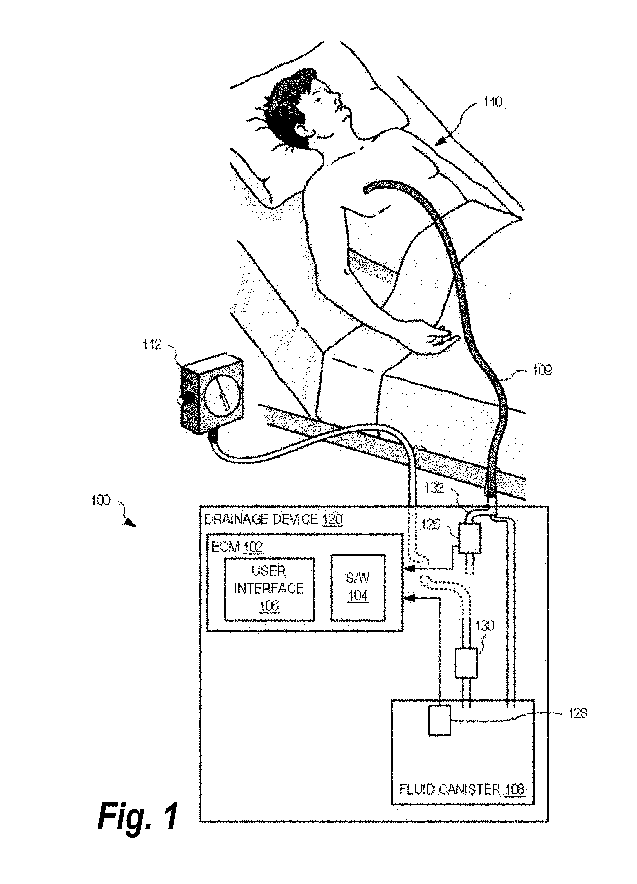
[0043]Embodiments of the present invention will be described in detail with respect to a device, system and method for measuring fluid volumes from an external source such as a chest cavity of a patient. Turning now to FIG. 1 a device embodying features of the present invention, sometimes referred herein as fluid analyzer, and generally designated by the numeral 100, is depicted.

[0044]FIG. 1 shows one exemplary fluid analyzer 100 for determining volume and / or flow of fluid draining from source such as a chest cavity of a patient 110. In the example of FIG. 1, fluid analyzer 100 is implemented within a drainage device 120 that operates, for example, to collect fluid drained from a chest cavity of a patient 110 using a catheter or tubing such as a double-lumen catheter 109. In the example of FIG. 1, drainage device 120 is shown coupled to a vacuum source 112 to facilitate fluid drainage from patient 110.

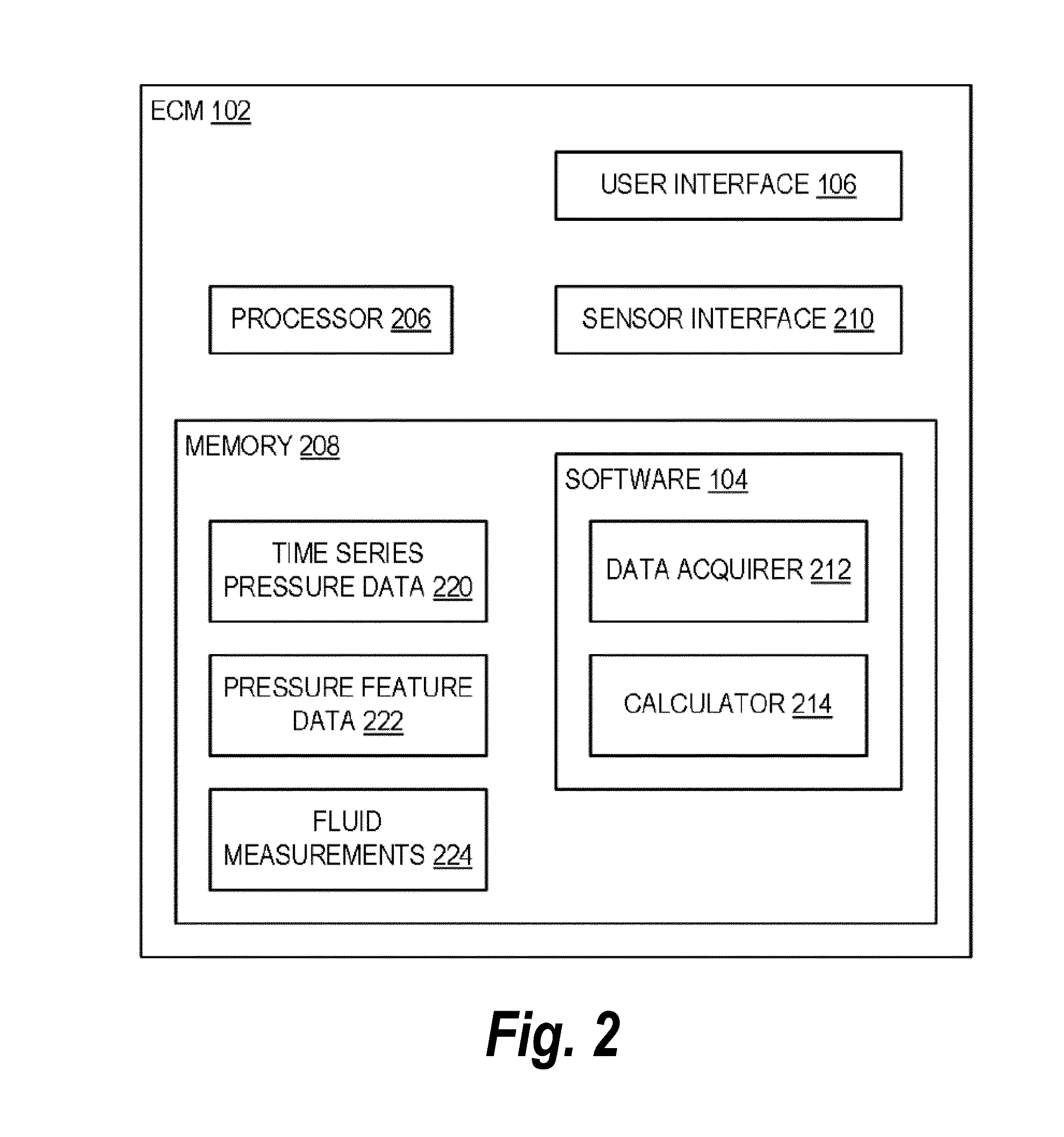
[0045]Drainage device 120 is shown to include an electronic control module (ECM) 1...


PUM


Abstract

Devices, computer readable programs and methods determine a patient parameter, including volume and / or flow rate of a fluid draining through a drain tube from a chest cavity of a patient, by using at least one pressure value at an end of the drain tube associated with a fluid collection canister and at least one pressure value within the drain tube at a location distant from the collection canister. The pressure values are processed with a non-linear solver to determine the patient parameter.

Description

RELATED APPLICATIONS[0001]This application claims priority to a provisional application Ser. No. 61 / 794,712 filed Mar. 15, 2013, the entire content of which is hereby incorporated by reference.STATEMENT REGARDING FEDERAL SPONSORSHIP[0002]Embodiments of the present invention were not conceived or reduced to practice with Federal sponsorship or grants.FIELD OF THE INVENTION[0003]Embodiments of the present invention are directed to equipment and methods of treatment in which it is desired to know the amount of fluid removed from a source of fluid such as the chest cavity of an individual.BACKGROUND[0004]There are several disease states and injuries for which it is desirable to remove fluids from the chest cavity of the afflicted individual. Clinicians monitor the amount of fluid removed in order to determine the progression of the healing process, the progression of the disease and the function of the devices used to effect such drainage. Typically, the patient has a drainage tube inse...

Claims


Application Information

Patent Timeline
Patent Type & Authority Applications(United States)
IPC IPC(8): A61B5/00A61M1/00A61B5/03
CPCA61B5/7267A61B5/036A61B5/6852A61B5/7475A61B5/7225A61M1/008A61M1/0019A61B5/742A61M2205/3334A61M2205/3344A61M2205/3389A61M2205/52A61M2210/101A61B5/0816A61B5/4848G16H50/70A61M1/74A61M1/69A61M1/84
Inventor PEATFIELD, GREGKARWOSKI, TED
Owner ATRIUM MEDICAL
Why Eureka
Try Eureka