Guidewire
- Summary
- Abstract
- Description
- Claims
- Application Information
AI Technical Summary
Benefits of technology
Problems solved by technology
Method used
Image

Examples
first embodiment
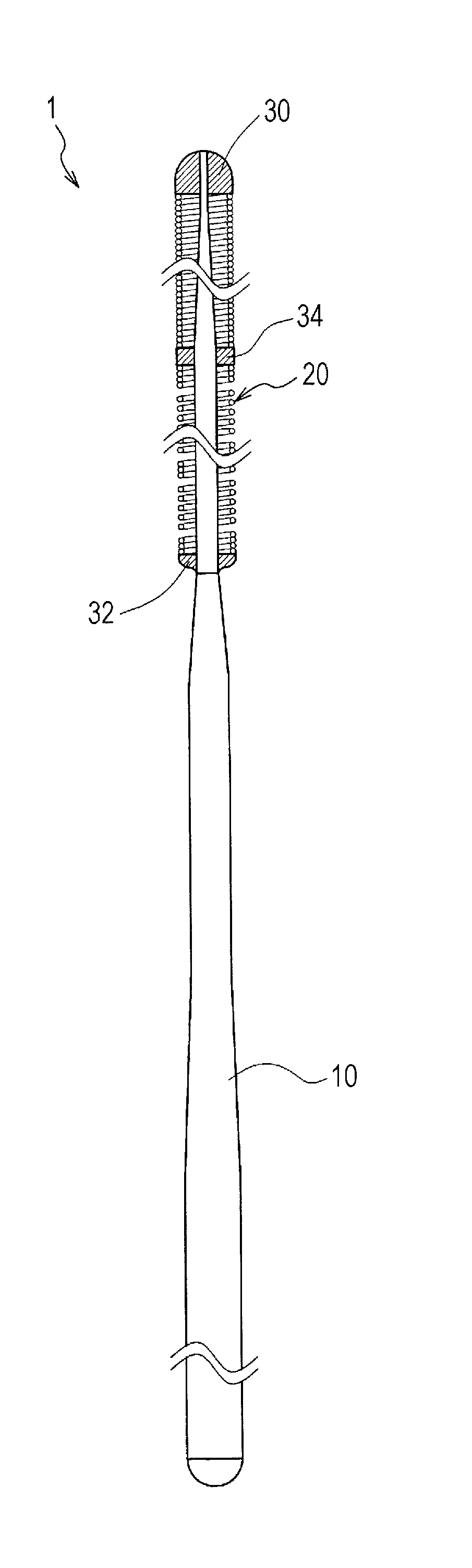
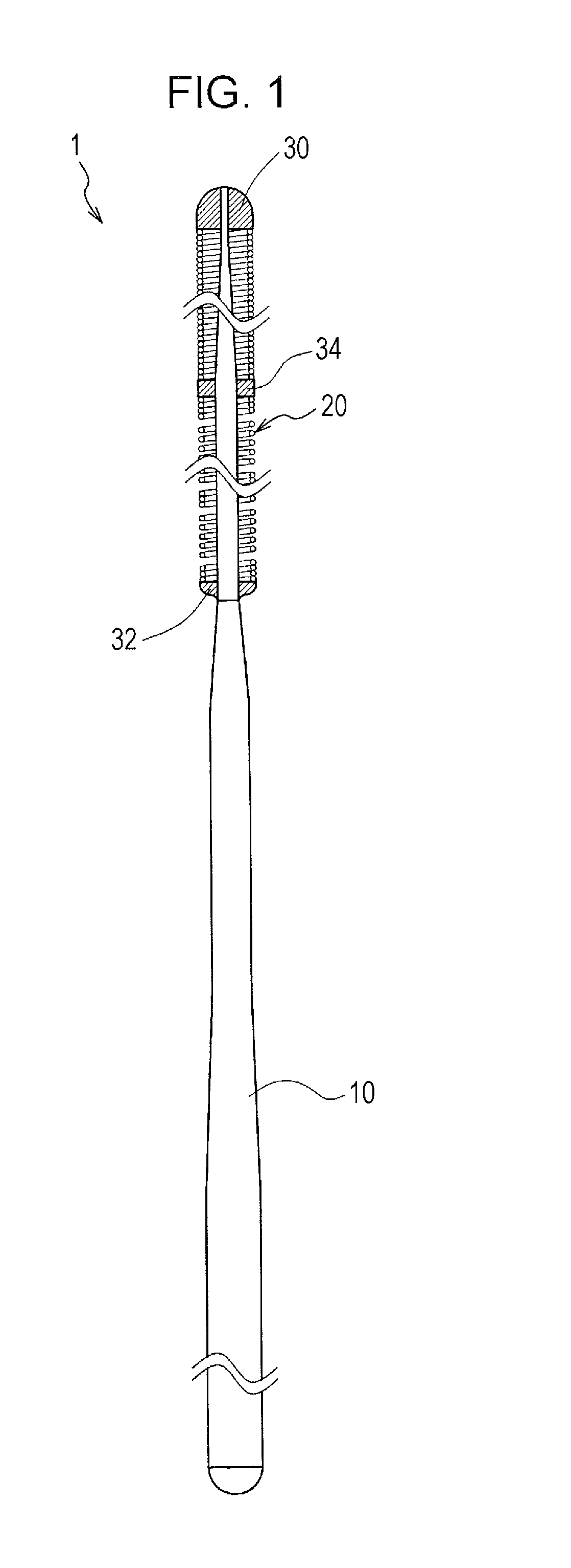
[0017]FIG. 1 is a diagram illustrating the structure of a guidewire 1 according to a As illustrated in FIG. 1, the guidewire 1 according to the present embodiment includes a core shaft 10 and a coil body 20 arranged so as to cover a distal portion of the core shaft 10.
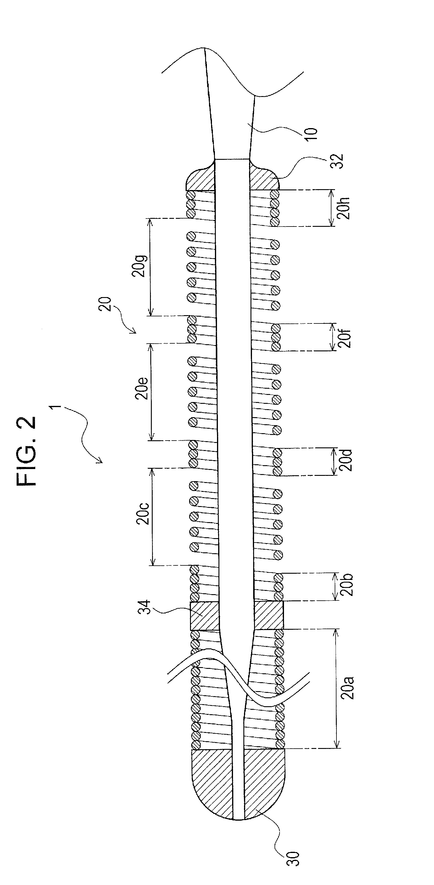
[0018]The core shaft 10 and the coil body 20 are bonded to each other with an adhesive (solder in the present embodiment). In the guidewire 1 according to the present embodiment, the core shaft 10 and the coil body 20 are bonded to each other with solder at a distal portion, a proximal portion, and an intermediate portion of the coil body 20. In the following description, a bonding portion for bonding the core shaft 10 to the distal portion of the coil body 20 is referred to as a distal bonding portion 30. A bonding portion for bonding the core shaft 10 to the proximal portion of the coil body 20 is referred to as a proximal bonding portion 32. A bonding portion between the distal bonding portion 30 and the proximal b...
second embodiment
[0028]In the guidewire 2 the loosely wound coil portion 22c is disposed so as to extend over substantially the entire region between the intermediate bonding portion 34 and the proximal bonding portion 32. Therefore, when the guidewire 2 is bent in a blood vessel, interference between wire portions of a coil body 22 can be reliably suppressed. As a result, stretching of the guidewire 2 in the blood vessel can be reliably suppressed, and the torque transmission performance of the guidewire 2 that is bent in the blood vessel can be reliably maintained.
[0029]FIG. 4 is an enlarged sectional view of a distal portion of a guidewire 3 according to a third embodiment of the present invention. The structure of the guidewire 3 according to the third embodiment illustrated in FIG. 4 is similar to that of the above-described guidewire 2 according to the second embodiment except for the following two points.
[0030]That is, in the guidewire 2 according to the second embodiment, the core shaft 10 ...
third embodiment
[0033]With the guidewire 3 the risk that the width of the bonding portions will be excessively large can be more reliably reduced. The reason for this will now be described.
[0034]In the case where the core shaft 12 is shaped such that the diameter thereof decreases toward the distal end as in the present embodiment, the gap between the inner peripheral surface of a coil body 23 and the outer peripheral surface of the core shaft 12 gradually increases toward the distal end. Therefore, a larger amount of adhesive is used at a distal bonding position than at a proximal bonding position.
[0035]In the present embodiment, as described above, the densely wound coil portion 23b at the distal end of the region between the intermediate bonding portion 34 and the proximal bonding portion 32 is longer than the densely wound coil portion 23d at the proximal end of the region between the intermediate bonding portion 34 and the proximal bonding portion 32. Therefore, even when a large amount of ad...
PUM
 Abstract
Description
Claims
Application Information