
Cruciate-retaining tibial prosthesis

a tibial prosthesis and cruciate technology, applied in the field of orthopaedic prosthesis systems, can solve the problems of joint pain, interference with normal use of the joint, and weak attachment strength

Active Publication Date: 2014-10-30
MAKO SURGICAL CORP
View PDF6 Cites 4 Cited by
  • Summary
  • Abstract
  • Description
  • Claims
  • Application Information

AI Technical Summary

Benefits of technology

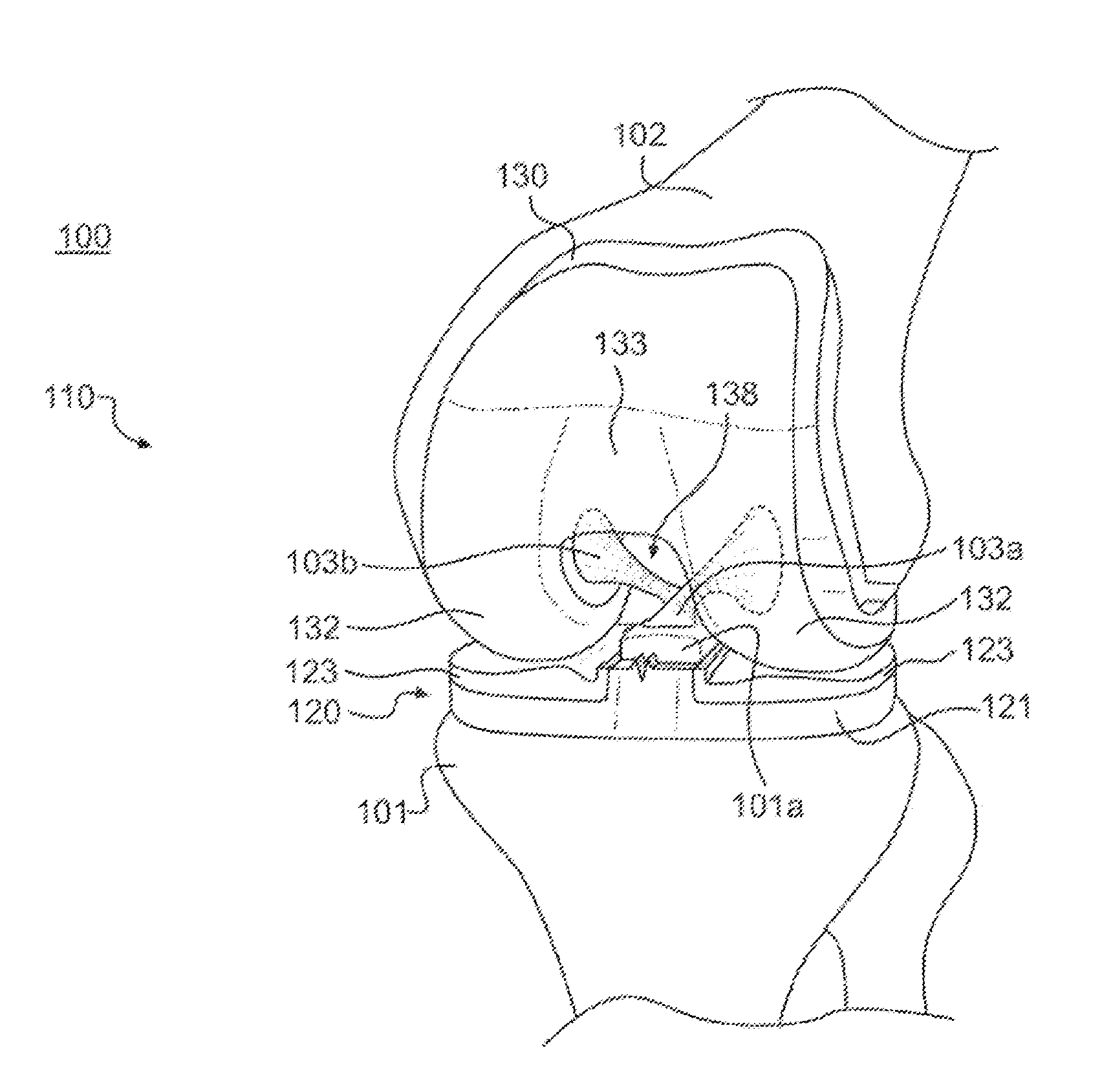
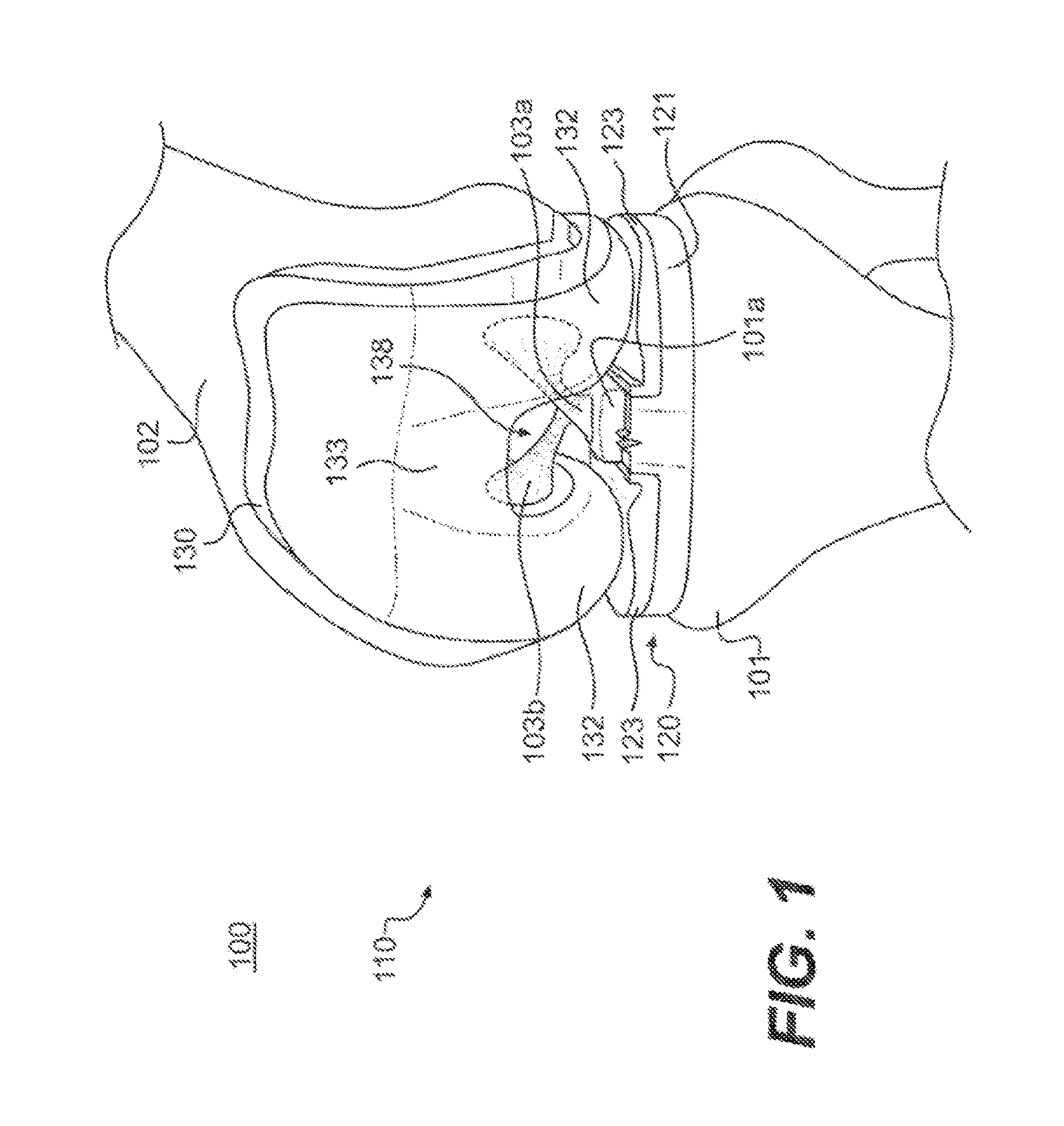
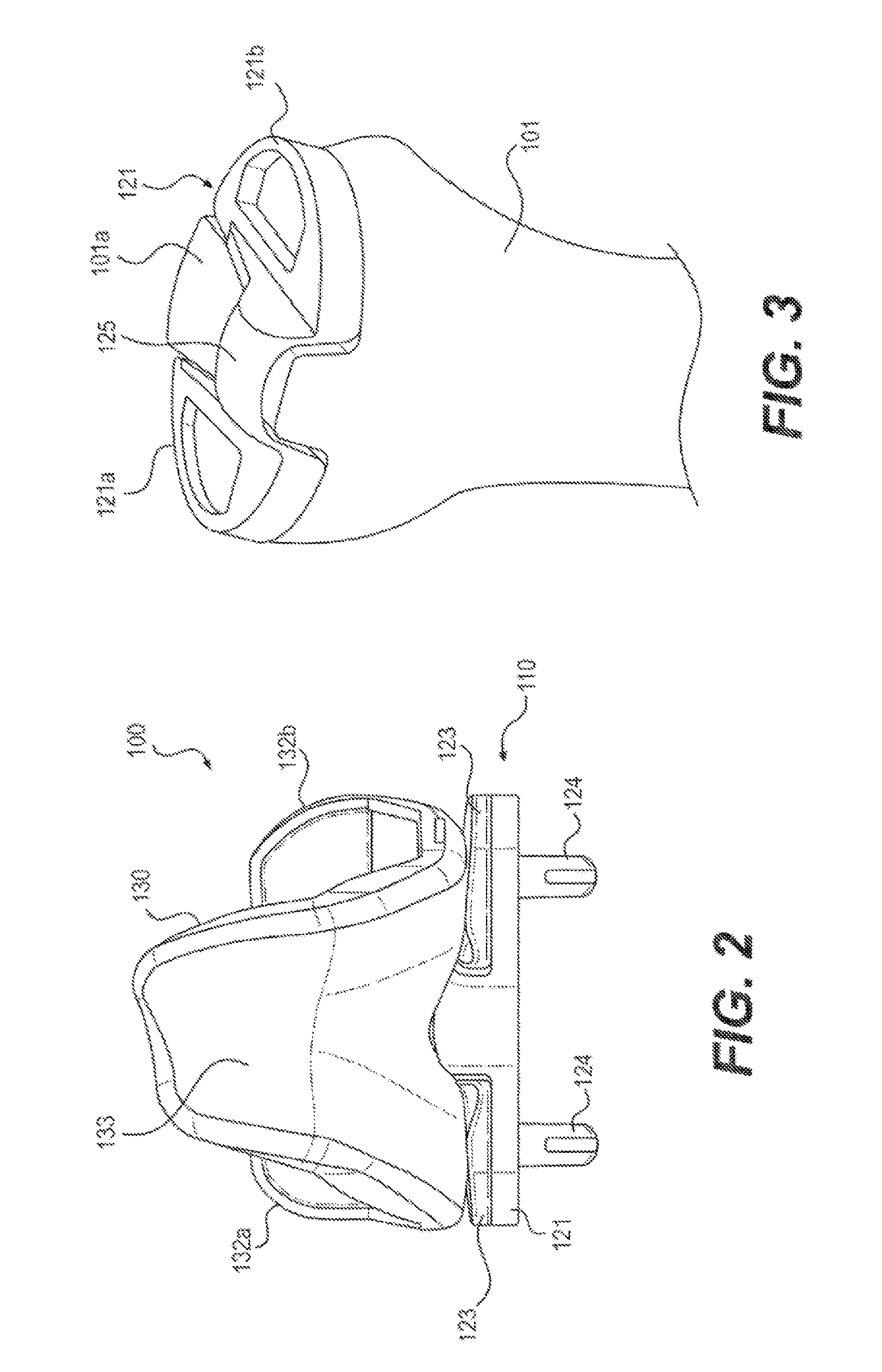
This patent is about a new design of a tibial prosthesis that can be used to replace a part of the knee joint. The prosthesis has two parts that are separated by a gap, and there is a bridge that connects the two parts. The bridge is designed to fit between the two parts. This design helps to replicate the natural movement and structure of the knee joint, which can improve the function and comfort of the prosthesis. The prosthesis also has a curved shape that matches the contour of the natural knee joint, which can help to reduce pain and improve stability. The patent mentions various other features of the design, such as the use of angled walls and an arched bridge, which can further enhance the performance of the prosthesis.

Problems solved by technology

When the knee joint is damaged, the natural bones and cartilage that form the joint may be unable to properly articulate, which can lead to joint pain and, in some cases, interfere with normal use of the joint.
Unfortunately, this surrounding tissue provides much of the attachment strength that counteracts the tension applied by the cruciate ligaments.
Consequently, removal of this tissue can substantially weaken the attachment strength of the tibial eminence.
One major problem associated with cruciate-retaining tibial procedures is the incidence of failure of the tibial eminence due to the removal of surrounding supporting structure that is required by the installation of the tibial prosthetic.
This increase in width resulted in a corresponding decrease in the structural integrity of the connecting structure.
Although these systems may enhance the overall strength of the implant and allow for a wider intercondylar passage, they require removal of a significant amount of subsurface tissue, which can undermine the area surrounding the tibial eminence.
This may compromise the strength of the area beneath the tibial eminence, which may result in increased incidence of failure of the tibial eminence.

Method used


Image

  • Cruciate-retaining tibial prosthesis
  • Cruciate-retaining tibial prosthesis
  • Cruciate-retaining tibial prosthesis

Examples


Embodiment Construction

[0044]Reference will now be made in detail to exemplary embodiments of the present disclosure, examples of which are illustrated in the accompanying drawings. Wherever possible, the same reference numbers will be used throughout the drawings to refer to the same or similar parts.

[0045]A healthy knee joint comprises the interface between the distal end of the femur and the proximal end of the tibia. If the healthy knee joint becomes damaged due, for example, to injury or disease, knee surgery may be required to restore normal structure and function of the joint. If the damage to the knee is severe, total knee arthroplasty (“TKA”) may be required. TKA typically involves the removal of the damaged portion of joint and the replacement of the damaged portion of the joint with one or more prosthetic components.

[0046]In some TKA procedures, one or more of cruciate ligaments (including anterior cruciate ligament and / or posterior cruciate ligament) may be left intact, to be re-used with the ...


PUM


Abstract

A tibial prosthesis comprises a medial base portion configured to engage a medial surface of a tibia and a lateral base portion configured to engage a lateral surface of the tibia. At least a portion of the medial and lateral base portions are separated by a passage interposed therebetween. The tibial prosthesis also comprises a bridge coupling the medial base portion and the lateral base portion, wherein at least a portion of the bridge is elevated above a portion of the passage between the medial base portion and the lateral base portion. The bridge may define an underlying area that receives at least a portion of a tibial eminence when the tibial prosthesis is engaged with the tibia, wherein the height of the bridge varies in a superior direction across the passage.

Description

CROSS-REFERENCE TO RELATED APPLICATIONS[0001]This application is a continuation-in-part of U.S. patent application Ser. No. 13 / 340,645, filed Dec. 29, 2011, the disclosure of which is incorporated by reference herein in its entirety.TECHNICAL FIELD[0002]The present disclosure relates generally to orthopedic prosthesis systems used in knee joint replacement surgeries and, more particularly, to a tibial prosthesis used in cruciate-retaining knee arthroplasty procedures.BACKGROUND[0003]The knee joint comprises the interface between the distal end of the femur and the proximal end of the tibia. In a properly-functioning knee joint, medial and lateral condyles of the femur pivot smoothly along menisci attached to respective medial and lateral condyles of the tibia. When the knee joint is damaged, the natural bones and cartilage that form the joint may be unable to properly articulate, which can lead to joint pain and, in some cases, interfere with normal use of the joint.[0004]In some si...

Claims


Application Information

Patent Timeline
Patent Type & Authority Applications(United States)
IPC IPC(8): A61F2/38
CPCA61F2/389A61F2002/30688
Inventor IRWIN, RONALD R.OTTO, JASON KARLABBASI, ALI ZAFARNADZADI, MARK ELLSWORTH
Owner MAKO SURGICAL CORP
Learn More