Projected image planogram system

a projection image and planogram technology, applied in the field of retail displays, can solve the problems of time-consuming and costly display setting using traditional paper planograms, and the possibility of error in recreating the merchandise display in the store,

Active Publication Date: 2014-10-30
STEVNACY LLC
View PDF3 Cites 30 Cited by
  • Summary
  • Abstract
  • Description
  • Claims
  • Application Information

AI Technical Summary

Benefits of technology

[0034]In another feature and advantage of embodiments of the invention, the system accepts as an input a planogram image created outside of the PIP system. The PIP system uses image recognition algorithms to identify fixtures and merchandise within the image.
[0035]In another feature and advantage of embodiments of the invention, the information and images recorded are sent to other locations for recreation.
[0036]In another feature and advantage of embodiments of the invention, at the retail store or other environment where the planogram or design is to be set or recreated, a computer with projector attached displays aspects of the planogram or design on the display board or the display surface area. In embodiments, the display can include: an image of the completed planogram or design, illuminated shapes or images identifying fixture type, illuminated shapes or images identifying fixture locations, illuminated shapes or images identifying merchandise to be displayed, illuminated shapes or images identifying merchandise locations, and illuminated shapes or images identifying other items used or incorporated within the design. The illuminated shapes or images may incorporate the use of numerous colors, shapes, designs, textures, photographic images or other equivalents for delineation or identification.
[0037]In another feature and advantage of embodiments of the inve

Problems solved by technology

Planogramming is one of the more costly payroll functions in retail.
Thus, display setting using traditional paper planograms is time-consuming and costly.
Further, the existing process used by retailers for setting planograms leaves much room for error in recreating the merchandise display in the store.
An error in the placement of one fixture when setting the plano

Method used


Image

  • Projected image planogram system
  • Projected image planogram system
  • Projected image planogram system

Examples


Embodiment Construction

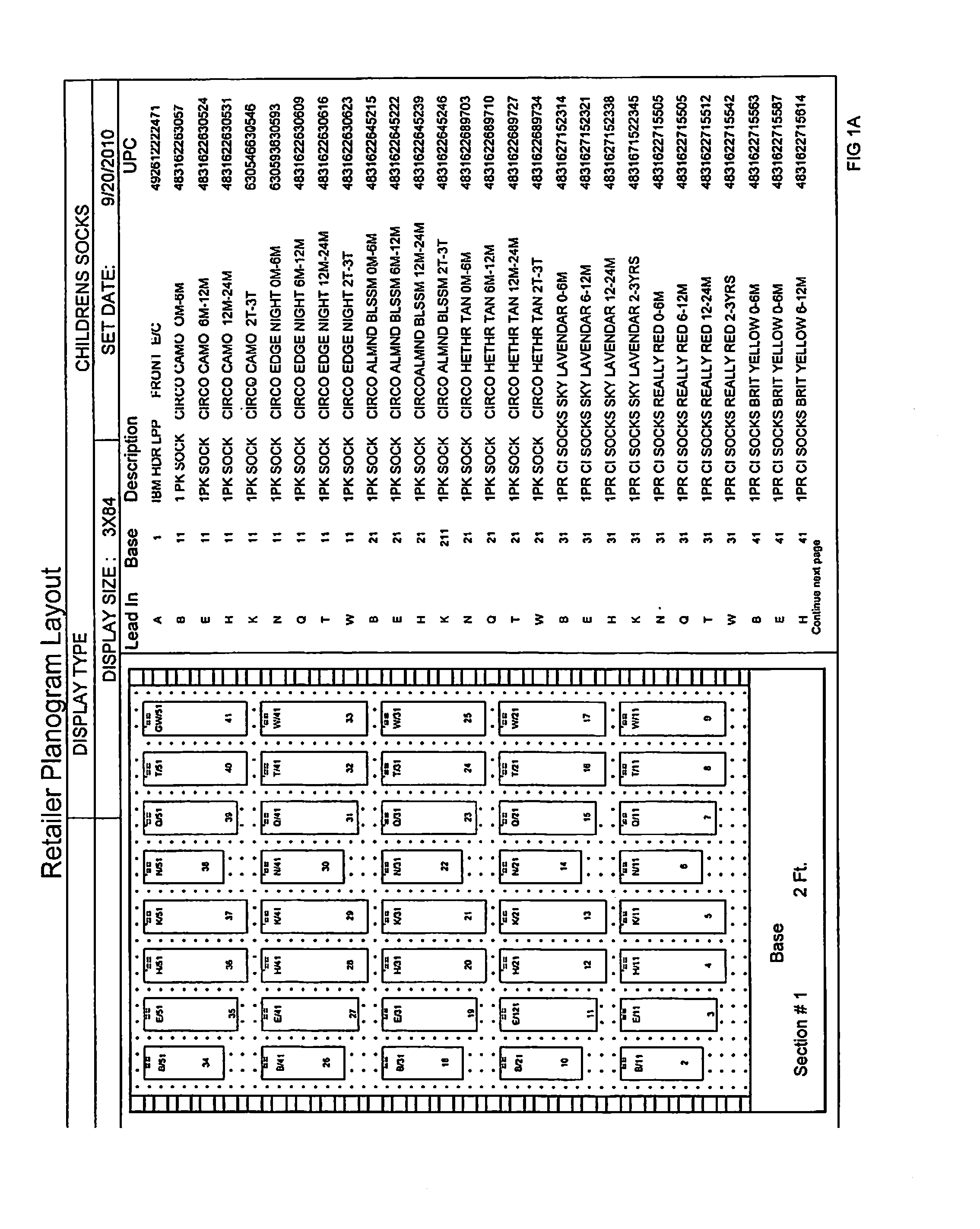
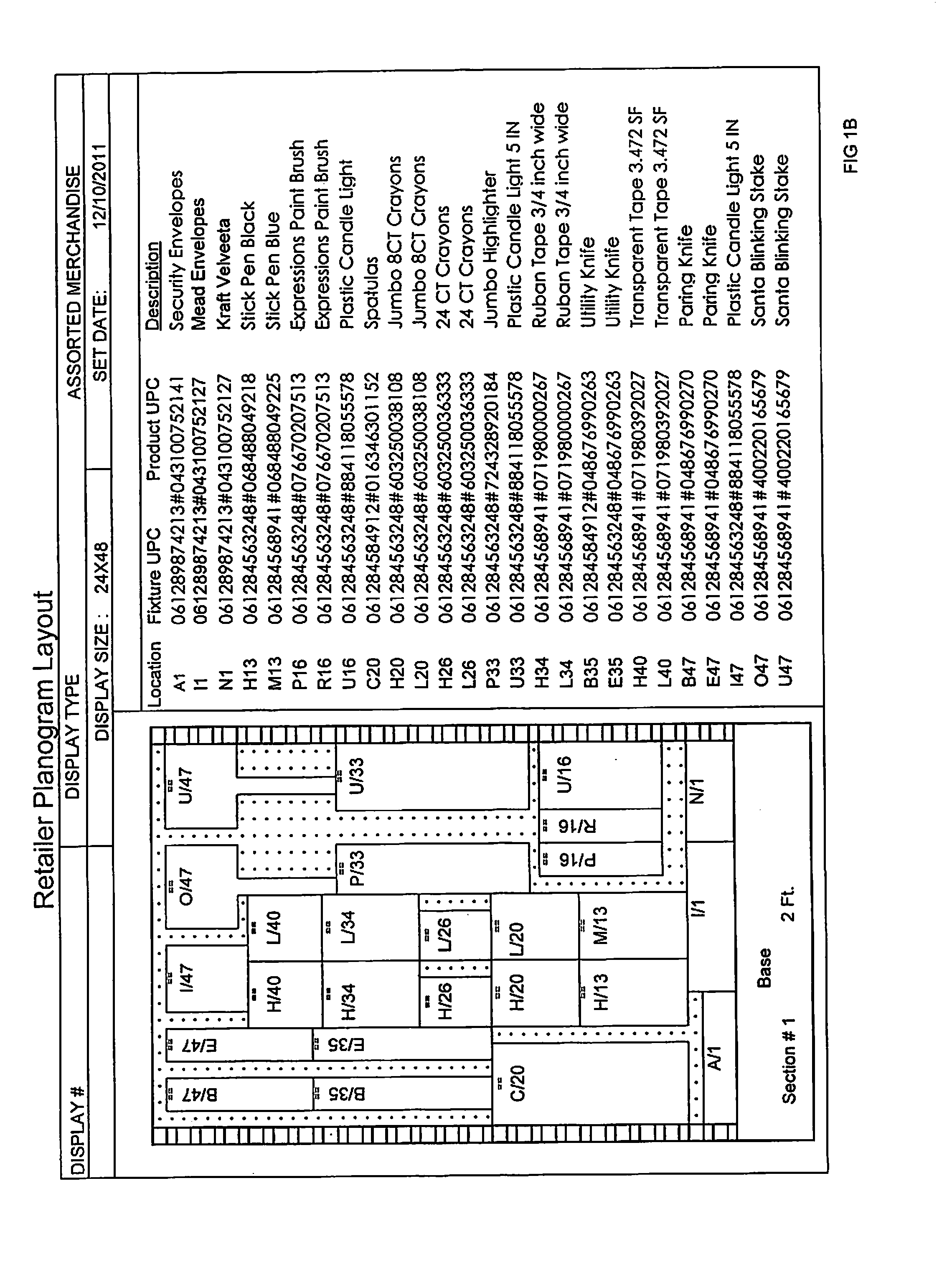
[0071]Representations of current methods for recording and distributing planogram information are shown in FIGS. 1A and 1B. Product layout for the planogram are depicted in a drawing showing specific fixture and merchandise locations along with written detail on the fixture and product used in the planogram.

[0072]A more detailed description of the various embodiments of the present invention is provided with further references in the drawings beginning with FIG. 2A, a depiction of a store display section 102 or merchandise display structure, which in an embodiment comprises a display board with holes having the usual alignment of 1″ spacing both vertical and horizontal 103 with a metal stanchion 104. Store display section or merchandise display structure 102 includes various known merchandise display structures, display devices, systems and structures for supporting fixtures and displaying merchandise. Optional store signage 105 for marketing is attached across the top of the displa...


PUM


Abstract

A method of generating a planogram for a retail display. The method includes selecting a merchandise item having a merchandise identifier; selecting a fixture associated with the merchandise item, the fixture having a fixture identifier; determining a display location for the fixture or for the merchandise item, the display location being one of a plurality of display locations of a merchandise display structure, the merchandise display structure being configured to receive the fixture and to display the merchandise item; generating a marker code based on the merchandise identifier and the fixture identifier, the marker code identifying the merchandise item and the fixture; and generating a planogram data file, the planogram data file including data corresponding to the marker code and the display location, the marker code identifying the merchandise and fixture.

Description

RELATED APPLICATION[0001]This application is a continuation-in-part of U.S. patent application Ser. No. 13 / 674,627 filed Nov. 12, 2012, which claims benefit of U.S. Provisional Patent Application No. 61 / 558,834, filed Nov. 11, 2011 and U.S. Provisional Patent Application No. 61 / 680,576, filed Aug. 7, 2012, which applications are hereby incorporated by reference herein in their entirety.TECHNICAL FIELD[0002]The invention relates generally to retail displays, and more particularly, to planograms used in displaying merchandise in a retail display.BACKGROUND[0003]The retail industry uses a process called planogramming for creating and communicating the design of a merchandise layout within a given category to be replicated at multiple retail locations. Typically created by corporate management or other centralized decision-makers, a planogram is an illustration, drawing, or instructions showing where products should be placed on pegboard or other display background surfaces. It also det...

Claims


Application Information

Patent Timeline
IPC IPC(8): G06Q10/08
CPCG06Q10/087
Inventor WINKEL, JAMES T.
Owner STEVNACY LLC
Why Eureka
Try Eureka