Zipline braking system

a braking system and zipline technology, applied in the field of ziplines, can solve the problems of inability to meet the needs of zipline riders, inability to adjust to the speed of the zipline, and pain in the neck or back of zipline riders,

Inactive Publication Date: 2014-11-06
TAG ADVENTURE TOURS
View PDF11 Cites 17 Cited by
  • Summary
  • Abstract
  • Description
  • Claims
  • Application Information

AI Technical Summary

Benefits of technology

[0011]According to another aspect of the invention, there is provided a method for decelerating a zipline rider on a rider carrier travelling on a zipline cable from an origination supporting member toward a destination supporting member having a damper, the method comprising: providing a primary stopping member for asserting a deceleration force on the rider carrier in a direction away from the destination supporting member; providing a secondary stopping member for engaging the damper; providing a tension line tied to the primary stopping member; and, engaging the tension line with the secondary stopping member such that movement of the primary stopping member towards the destination supporting member after engagement with the rider carrier leads the tension line to cause the secondary stopping member to move towards the destination supporting member and compression of the damper.

Problems solved by technology

As such, these systems are susceptible to human errors.
In addition, zipline riders often complain that present braking systems cause pain to their necks or backs due to the dramatic speed decrease upon a zipline rider reaching the end of the zipline.
Some braking systems also create a loud crashing sound that is not appealing to zipline riders.

Method used


Image

  • Zipline braking system
  • Zipline braking system
  • Zipline braking system

Examples


Embodiment Construction

[0037]The description which follows and the embodiments described therein are provided by way of illustration of an example or examples of particular embodiments of the principles of the present invention. These examples are provided for the purposes of explanation and not limitation of those principles and of the invention. In some instances, certain structures and techniques have not been described or shown in detail in order not to obscure the invention.

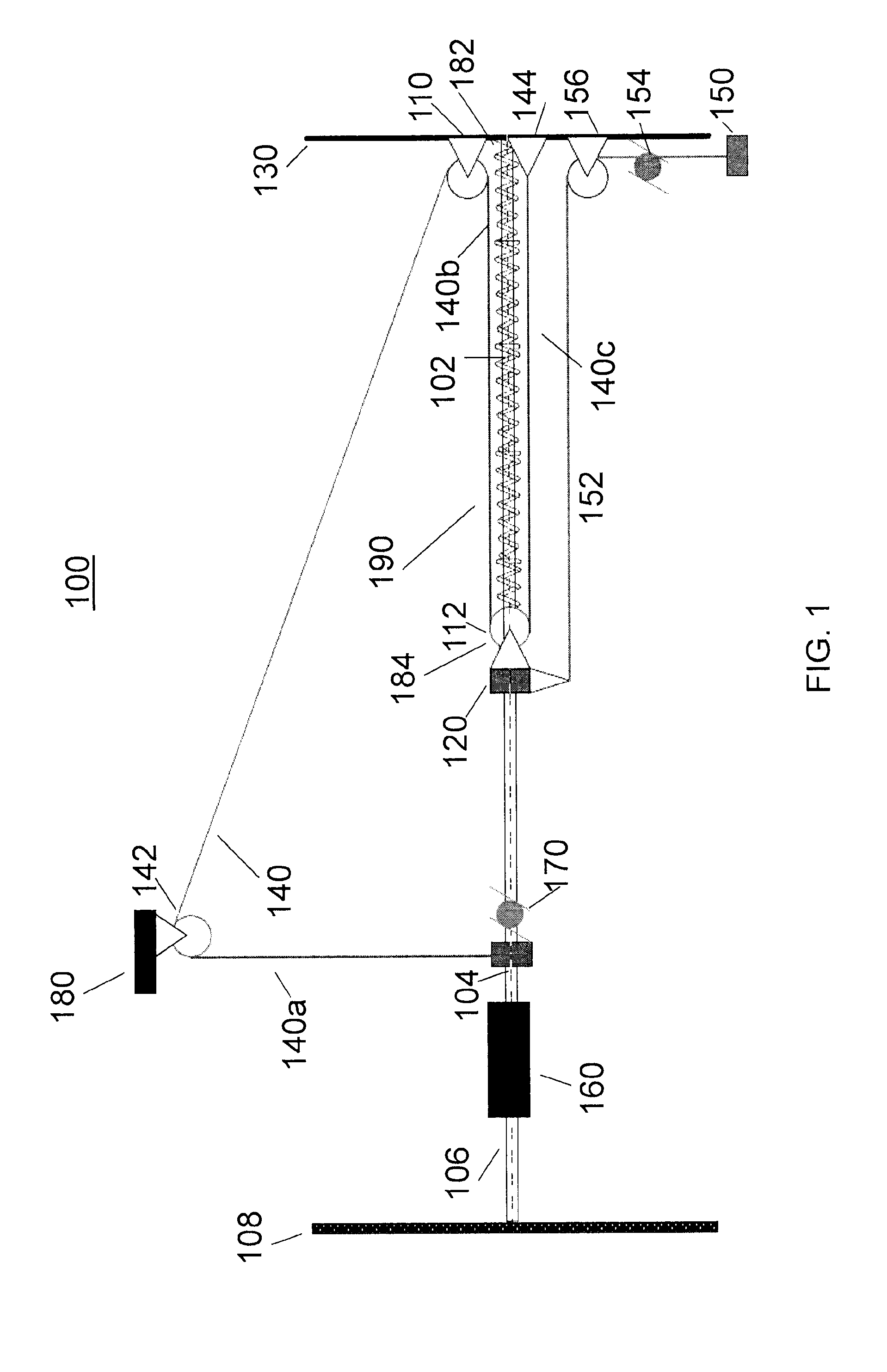
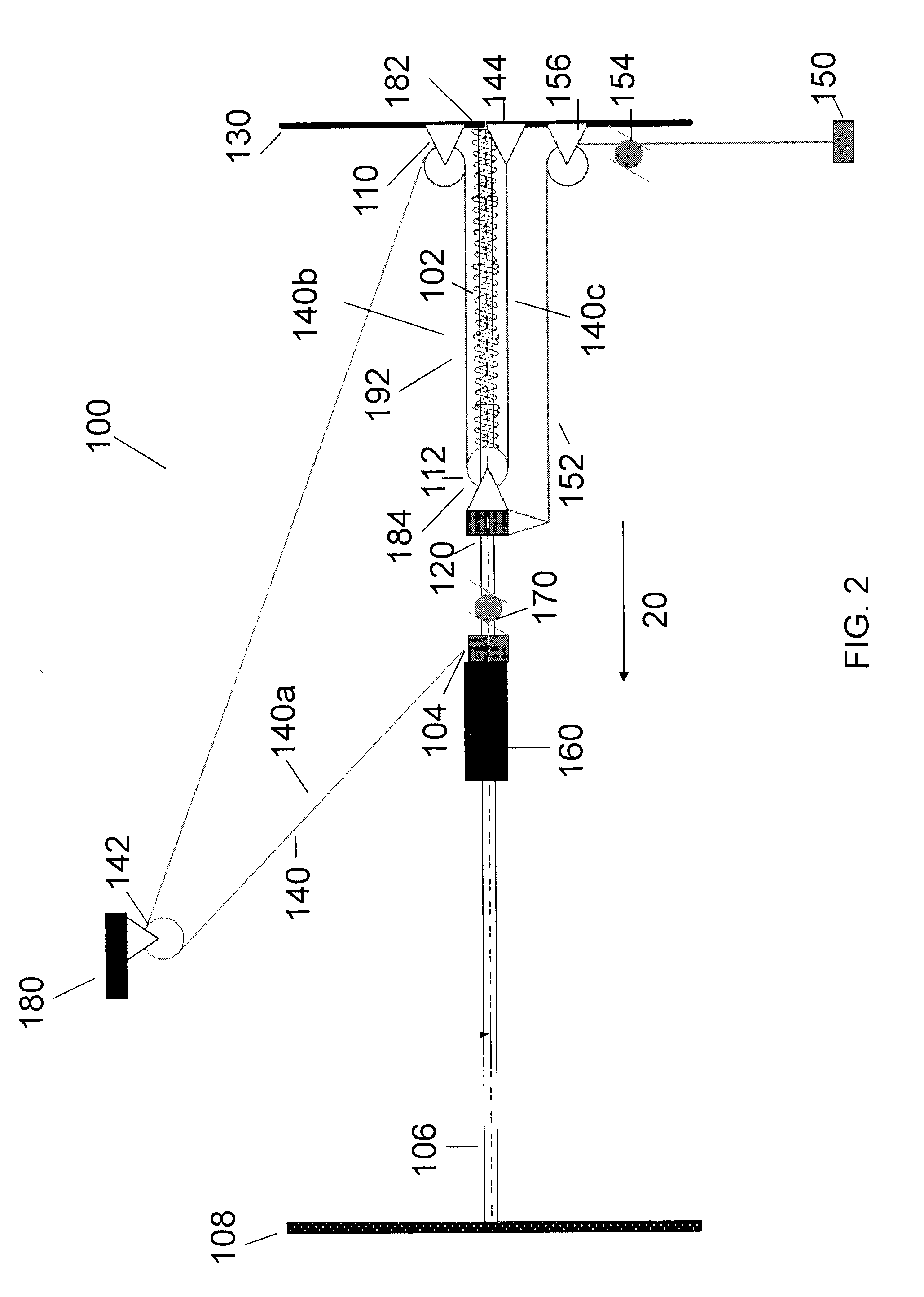
[0038]The present invention is directed generally to a braking system that may enhance the experience of zipline riders through reduction in jarring and abrasive braking. In addition, the present invention may provide for safety redundancy whereby braking and stopping of a zipline rider is done by a primary stopping member, a damper, and / or a secondary stopping member.

[0039]According to one embodiment, the present invention provides a zipline braking system that is based partially on conversion of kinetic energy to potential energ...


PUM


Abstract

A zipline braking system comprising a zipline cable and a destination supporting member; a rider carrier coupled to the zipline cable for movement towards the destination supporting member, such movement generating kinetic energy; a damper having a posterior end and an anterior end and connected to the destination supporting member at the posterior end; a tension line; a stopping member coupled to the zipline cable and the tension line; and the tension line for transferring the kinetic energy to the damper upon the rider carrier engaging the stopping member in movement to the destination supporting member.

Description

[0001]This application claims the benefit of U.S. Provisional Patent Application No. 61 / 570,410, filed Dec. 14, 2011.FIELD OF THE INVENTION[0002]The invention relates to ziplines, and more specifically to a zipline braking system for decelerating a zipline rider as the rider reaches the end of the zipline.BACKGROUND[0003]Ziplines allow riders to travel from one point to another. They are used for various purposes, including as thrill rides and tourist attractions. Ziplines generally include two supports and a cable suspending between the two. There is generally an area on each support, usually a platform, to allow riders to embark and disembark from the zipline. Harnesses and pulleys are used for transporting and providing support to the zipline riders.[0004]Several different zipline braking systems have been adopted by zipline operators. Some systems require a rider to move a static mass of springs whereas others incorporate a speed limiting trolley. Other zipline braking systems i...

Claims


Application Information

Patent Timeline
Patent Type & Authority Applications(United States)
IPC IPC(8): B61H9/02B61B7/00
CPCB61H9/02B61B7/00A63G21/20F16D63/008
Inventor HALLIDAY, DAVID J.STIEMER, SIEGFRIED F.
Owner TAG ADVENTURE TOURS
Why Eureka
Try Eureka