Combined gas-water tube hybrid heat exchanger

a technology of heat exchanger and water tube, which is applied in the field of heat exchanger, can solve the problems of increasing fabrication and installation costs, unnecessarily warm top casting, and failure to harness and recover the maximum amount of energy, and achieves the effect of simple and less costly construction techniques

Active Publication Date: 2014-11-06
INTELLIHOT
View PDF16 Cites 15 Cited by
  • Summary
  • Abstract
  • Description
  • Claims
  • Application Information

AI Technical Summary

Benefits of technology

[0009]The present invention is directed toward a heat exchanger comprising combined water and gas tubes, the heat exchanger is buildable with simpler and less costly construction techniques as compared to conventional gas-fired water tube heat exchangers. The present heat exchanger includes an cylindrical body including an upper section, a lower section, a side water jacket having a water outlet and surrounding the upper section and the lower section, a top water jacket disposed atop the upper section and a gas exhaust disposed below the lower section, wherein the water outlet is disposed substantially at the lower end of the side water jacket. The heat exchanger comprises a water cavity having a water inlet for receiving water, wherein the water inlet is disposed substantially at the lower end of the lower section and the water cavity is disposed substantially in the lower section, a gas cavity having a burner is disposed substantia

Problems solved by technology

However, the use of a ceramic disc inside the lumen takes up valuable heat exchanger footprint, increases fabrication and installation costs and fails to harness and recover the maximum amount of energy.
Poor heat recover

Method used


Image

  • Combined gas-water tube hybrid heat exchanger
  • Combined gas-water tube hybrid heat exchanger
  • Combined gas-water tube hybrid heat exchanger

Examples


Embodiment Construction

[0036]The term “about” is used herein to mean approximately, roughly, around, or in the region of. When the term “about” is used in conjunction with a numerical range, it modifies that range by extending the boundaries above and below the numerical values set forth. In general, the term “about” is used herein to modify a numerical value above and below the stated value by a variance of 20 percent up or down (higher or lower).

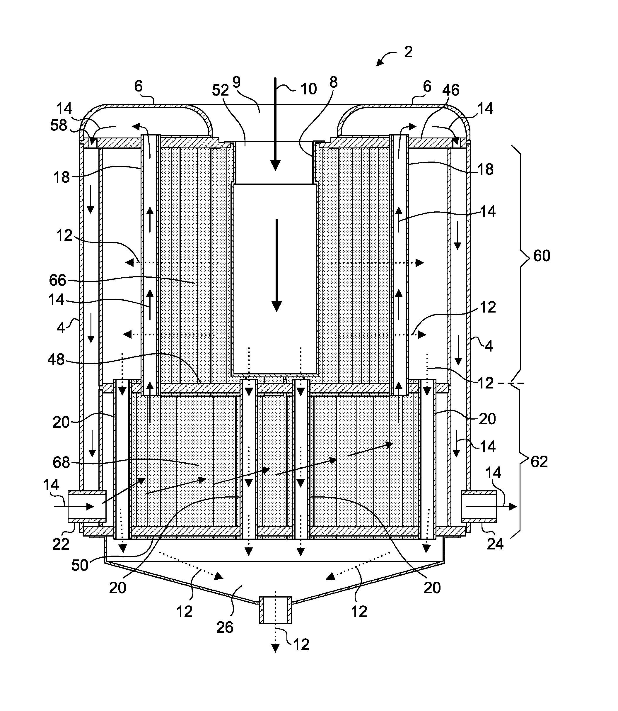
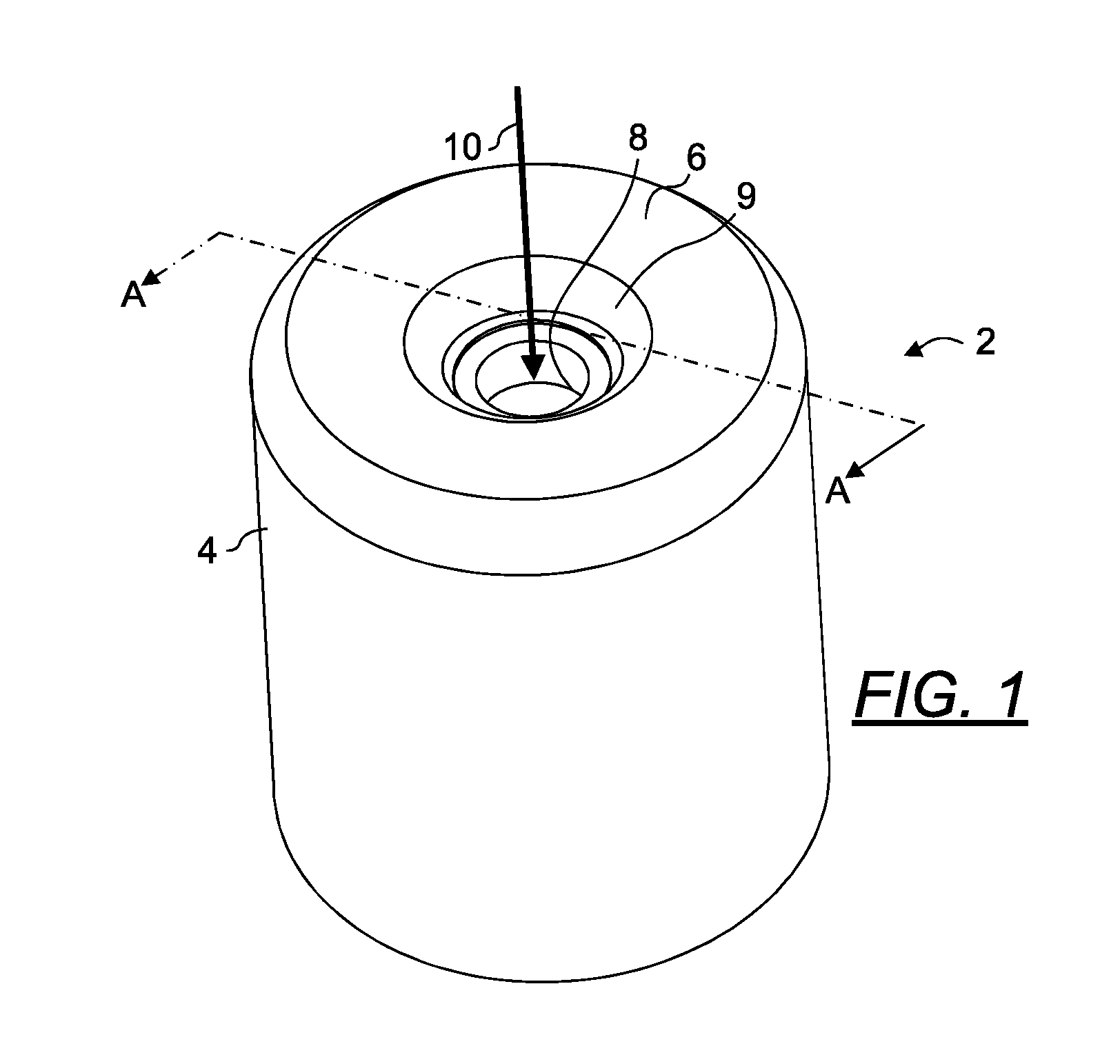
[0037]FIG. 1 is a top perspective view of a heat exchanger 2 of the present invention, depicting a cavity for receiving air / fuel mixture through the top surface of the heat exchanger 2. In use, an air / fuel mixture flow is provided in direction 10 to the burner 8 with the aid of a blower 28 (see FIG. 11). The external surfaces of the heat exchanger generally define an elongated cylindrical shaped body having a side water jacket 4, a top water jacket 6 and an opening 9 in the top water jacket 6.

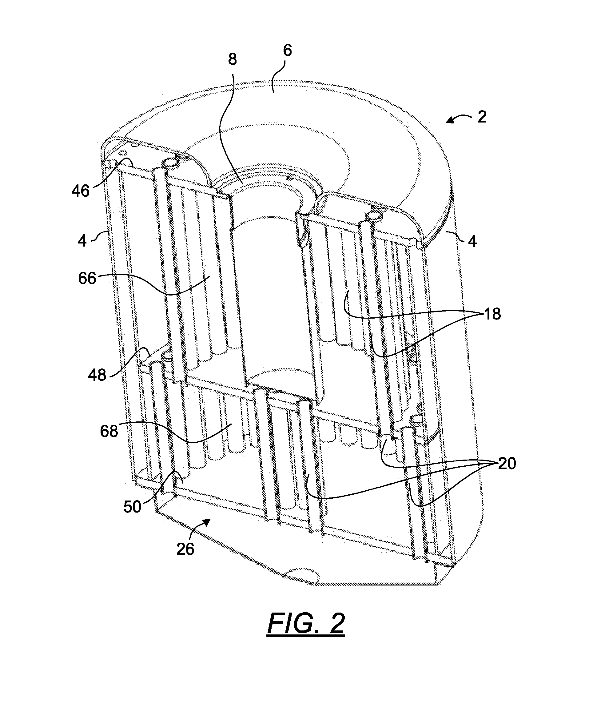
[0038]FIG. 2 is a top perspective sectional view as taken along line A...


PUM


Abstract

A heat exchanger having a cylindrical body comprising an upper section, a lower section, a side water jacket surrounding the upper and lower sections, a top water jacket disposed atop the upper section and a gas exhaust disposed below the lower section. A water cavity is disposed substantially in the lower section while a gas cavity having a burner is disposed substantially centrally within the gas cavity. A plurality of water tubes disposed in a ring formation, connect the water cavity through the gas cavity to the top water jacket and a plurality of gas tubes also disposed in ring formations, connect the gas cavity through the water cavity to the gas exhaust. At least one of the gas tubes ring has a diameter that is greater than that of the water tubes ring.

Description

PRIORITY CLAIM AND RELATED APPLICATIONS[0001]This application claims the benefit of priority from U.S. Ser. No. 61 / 545,385; a U.S. provisional application filed on Oct. 10, 2011 and PCT / US2012 / 048970, a PCT application filed Jul. 31, 2012. Each of said applications is incorporated by reference herein in its entirety.BACKGROUND OF THE INVENTION[0002]1. The Field of the Invention[0003]The present invention is directed generally to a heat exchanger. More specifically, the present invention is directed to a combined gas and water tube heat exchanger for use with a hot water heater.[0004]2. Background Art[0005]Fin-and-tube heat exchangers of conventional hot water systems often include a helical coil tube having fins disposed on external surfaces of the coil tube. Ceramic discs may be utilized to insulate direct heat of a burner from its adjacent components, such as a fan blower and other components disposed at the exhaust of a heat exchanger housing the burner. Typically, a fin-and-tube...

Claims


Application Information

Patent Timeline
IPC IPC(8): F24H1/14F28D7/16
CPCF24H1/145F28D7/16F28D7/1676F28D7/0075F24H1/285F24H1/287F24H1/44F24H9/0026
Inventor DEIVASIGAMANI, SRIDHARAKASAM, SIVAPRASAD
Owner INTELLIHOT
Why Eureka
Try Eureka