Power transmitting apparatus

a technology of power transmission apparatus and pressure member, which is applied in the direction of friction clutches, interengaging clutches, and clutches, etc., can solve the problems of abnormal noise and/or a feeling suggesting a malfunction in operation, and achieve the effect of suppressing the rotational reducing the vibration of the pressure member

Active Publication Date: 2014-11-06
FCC KK
View PDF3 Cites 24 Cited by
  • Summary
  • Abstract
  • Description
  • Claims
  • Application Information

AI Technical Summary

Benefits of technology

[0014]In some embodiments where the power transmitting apparatus comprises one or more slide-suppressing members for applying sliding resistance to the clutch member when the pressure member is rotated relative to the clutch member, it is possible to suppress rotational vibration of the pressure member by suppressing the rotation of the pressure member relative to the clutch member.
[0015]In some embodiments where the power transmitting apparatus comprises a press-contact assisting cam for increasing the press-contacting force acting on the driving-side clutch discs and the driven-side clutch discs by causing relative rotation of the pressure member and the clutch member and bringing them close to each other when the rotational driving power inputted to the input member is transmitted to the output member, and a back-torque limiting cam for releasing the press-contacting force acting on the driving-side clutch discs and the driven-side clutch discs by causing relative rotation of the pressure member and the clutch member and separating them from each other when a rotational speed of the output member has exceeded that of the input member, it is possible to prevent the pressure member from being rotationally vibrated due to transmission of vibration of an engine or other mechanism to the pressure member and thus to inhibit or prevent the vibration from being transmitted to operation means of a vehicle such as a clutch lever or other mechanism.
[0016]In some embodiments where the pressure member and the clutch member are assembled while being axially fitted with each other, and the slide-suppressing member is arranged on a fitting surface of the pressure member or of the clutch member, it is possible to suppress the rotational vibration of the pressure member without adverse influence to the operability of the pressure member.

Problems solved by technology

Accordingly, structural components of the power transmitting apparatus of the prior art have been found to interfere with each other to some extent and thus cause abnormal noises and / or a feeling suggesting a malfunction in operation.

Method used


Image

  • Power transmitting apparatus
  • Power transmitting apparatus
  • Power transmitting apparatus

Examples


Embodiment Construction

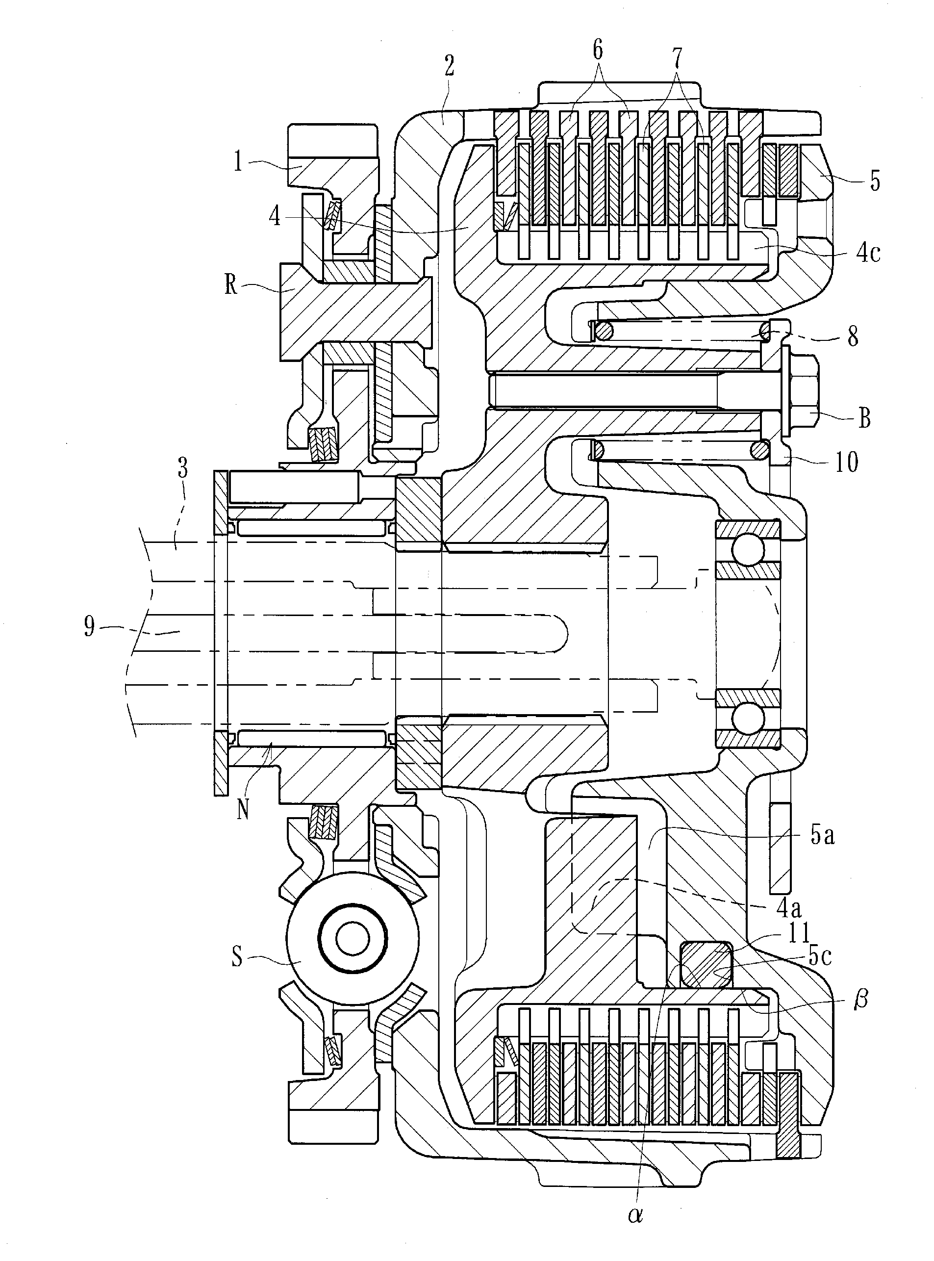
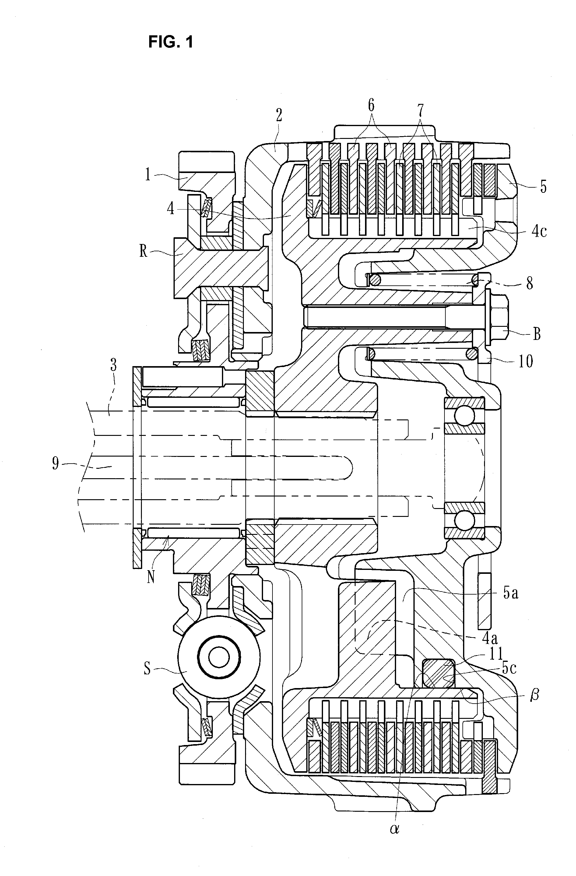
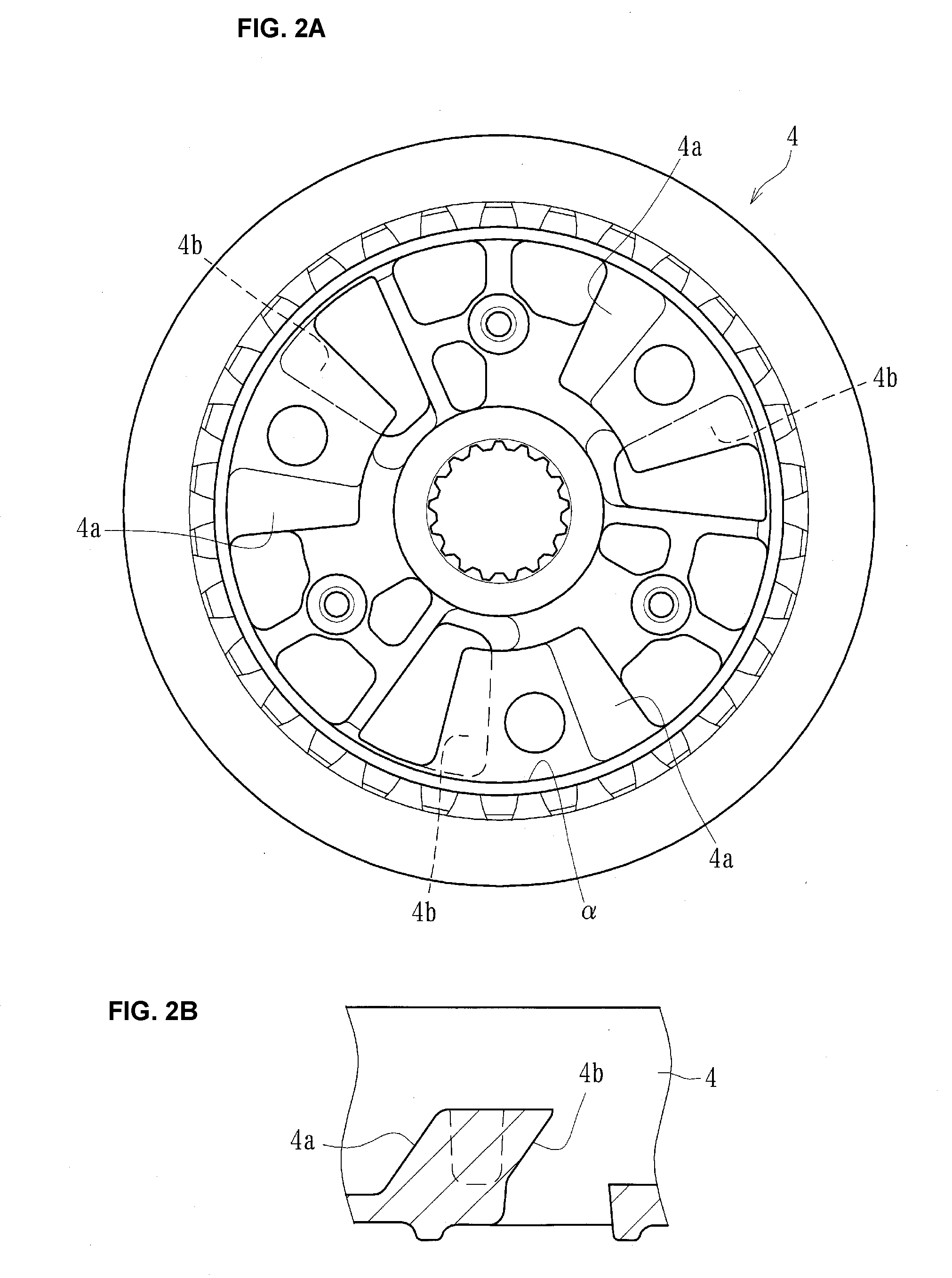
[0030]A power transmitting apparatus of the present disclosure can be mounted on a vehicle such as a motorcycle to arbitrarily transmit or cut off the driving power of an engine to or from a transmission or driving wheel. As shown in FIGS. 1-3, the power transmitting apparatus can comprise a clutch housing 2 formed by die-casting on which a gear 1 as an input member is mounted. In some embodiments, the power transmitting apparatus comprises a clutch member 4 connected to a shaft 3 (e.g., an output member). As illustrated, the power transmitting apparatus can comprise a pressure member 5 fitted on the clutch member 4 at its right-hand end (.e.g., with respect to the orientation of FIG. 1). In some cases, the power transmitting apparatus comprises driving-side clutch discs 6 mounted on the clutch housing 2, and driven-side clutch discs 7 connected to the clutch member 4. The power transmitting apparatus can include first and second cam surfaces 4a, 4b of a clutch member-side formed on...


PUM


Abstract

A power transmitting apparatus which can suppress the rotational vibrations by suppressing rotation of the pressure member relative to the clutch member is provided. The power transmitting apparatus can comprise a clutch housing rotatable together with an input member and a plurality of driving-side clutch discs mounted thereon; a clutch member with a plurality of driven-side clutch discs mounted thereon and interleaved with the driving-side clutch discs; and a pressure member axially movably relative to the clutch member to increase or release the press-contacting force acting on the driving-side clutch discs and the driven-side clutch discs. The power transmitting apparatus can further comprise one or more slide-suppressing members for applying sliding resistance to the pressure member when the pressure member is rotated relative to the clutch member.

Description

INCORPORATION BY REFERENCE TO ANY PRIORITY APPLICATIONS[0001]Any and all applications for which a foreign or domestic priority claim is identified in the Application Data Sheet as filed with the present application are hereby incorporated by reference under 37 CFR 1.57.BACKGROUND[0002]1. Technical Field[0003]The present inventions relate to a power transmitting apparatus for arbitrarily transmitting or cutting-off the rotational driving power of an input member to or from an output member[0004]2. Description of the Related Art[0005]In general, the power transmission apparatus for a motorcycle is intended to arbitrarily perform transmission or cutting-off of the driving power of an engine to or from a transmission and a driving wheel and comprises an input member connected to an engine-side, an output member connected to a transmission and a driving wheel-side, and a clutch member connected to the output member. The driving power can be transmitted by press-contacting a plurality of ...

Claims


Application Information

Patent Timeline
Patent Type & Authority Applications(United States)
IPC IPC(8): F16D13/54
CPCF16D13/54F16D13/56F16D2013/565F16D2300/22
Inventor ISOBE, KENICHIROUKAWASHIMA, SHIGEKIFURUHASHI, SHINJIANDO, GO
Owner FCC KK
Why Eureka
Try Eureka