Liquid filled bottle having a cover member with a label forming extension

a technology of liquid filled bottles and cover parts, applied in the field of containers, can solve the problems of high risk of breakage at the opening during transportation, and still contain a significant amount of plastic materials, and achieve the effect of improving the use of plastic materials

Active Publication Date: 2014-11-06
DES EAUX MINERALES DEVIAN +1
View PDF5 Cites 33 Cited by
  • Summary
  • Abstract
  • Description
  • Claims
  • Application Information

AI Technical Summary

Benefits of technology

[0007]A general object of the present invention is to provide liquid filled bottles having a narrow opening (

Problems solved by technology

Furthermore, risks of breakage at the opening during transport are higher with containers provided with apertur

Method used


Image

  • Liquid filled bottle having a cover member with a label forming extension
  • Liquid filled bottle having a cover member with a label forming extension
  • Liquid filled bottle having a cover member with a label forming extension

Examples


first embodiment

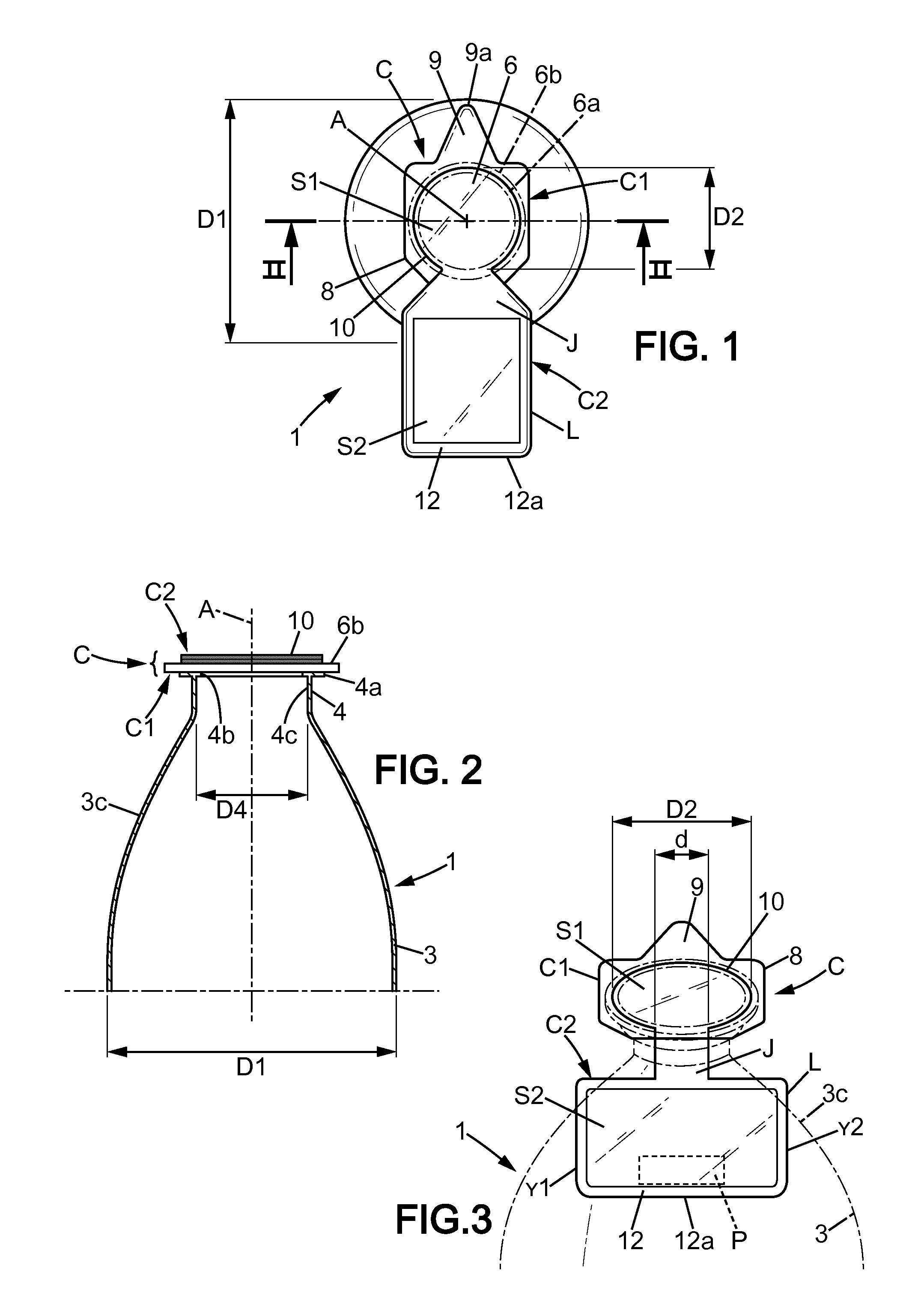
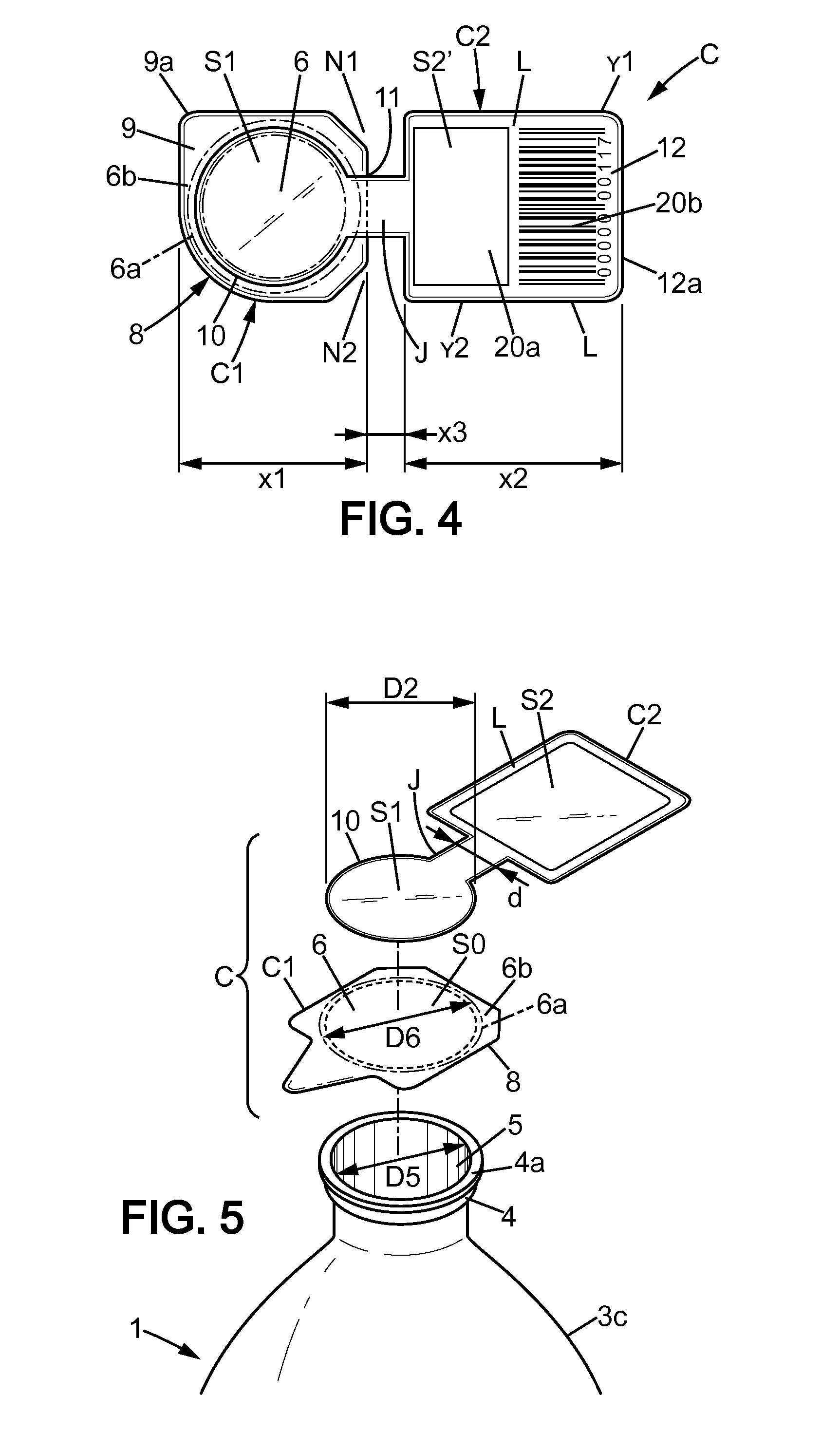
[0073]In the first embodiment shown in FIGS. 1-3 and 5 and in the variant of FIG. 4 or in the variant of FIG. 13 as well, the reinforcing portion 10 defines a substantially disc-shaped crown having a determined diameter D2. The inner diameter D5 of the opening is inferior to this diameter D2 and the annular fixing portion 6a of the central portion 6 is preferably continuously covered by the reinforcing portion 10 that creates an additional layer of material, thus stiffening and reinforcing the central portion 6. FIG. 13 illustrates a ring-like reinforcing portion 10 that defines an opening 10a (thus saving material). The reinforcing portion 10 may be directly fastened to all or a part of the support surface S0. The reinforcing portion 10, when shaped as a ring in particular, partly covers the central portion 6.

[0074]Referring to FIG. 4, it can be seen that the reinforcing portion 10 may be of smaller size than the ring 4a of the neck 4, so as to save material. In this case, the rein...

second embodiment

[0083]While FIGS. 1 and 3-5 show a label portion L of area at least equal to the area of the closing portion 6, a ratio about 3:4 (this ratio being preferably not inferior to 1:2) between the surfaces S2 and S1 may also be satisfactory as shown in FIG. 7. In this second embodiment, the reinforcing portion 10 is similar to the reinforcing 10 portion show in FIGS. 1, 3 and 5 but the surface S2 defined by the label portion L is smaller. In this case, the barcode 20b could be removed from the top face of the label portion L (and possibly displayed on the other face). It should be also noted that the closing element C1 is unchanged as compared to FIGS. 1, 3 and 5.

[0084]In order to increase visibility of the label information displayed by the label portion L, the label element C2 of the cover member C may be provided with at least one and preferably two notches N1, N2. A junction portion J (here narrower than the central portion 6) is arranged between the two notches N1, N2 to form a hing...

fifth embodiment

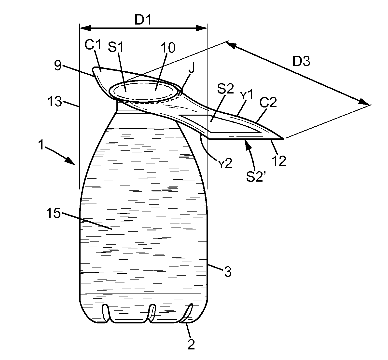
[0103]Now referring to FIG. 10, a fifth embodiment is shown in which the body 3 has a generally squared cross-section, inscribed in an imaginary encasing body 13 that corresponds to a cylinder. The narrow opening 5 is here circular but any other suitable shape could be used. For instance, the narrow opening 5 could be triangularly shaped to form a spout.

[0104]The free end 12 of the label portion L protrudes beyond this imaginary encasing body 13. The label element C2 made of the single piece multilayer film has an elliptic shape with the long axis defining the length D3 of the cover member C. The reinforcing portion 10 is arranged in a first half of the ellipse and the surface S2 for displaying label information is located in the second half, so that this second surface S2 is entirely offset relative to the annular fixing portion 6a used for the fixing of the closing member C1. The surface S1 arranged in the first half may be also used to display information. It can be seen that the...


PUM


Abstract

The plastic bottle (1) is filled with liquid and provided with a neck (4) that defines a narrow opening (5) with an inner diameter typically inferior to 40 mm. A flexible sheet-like cover member (C), having a lower closing element (C1) and an upper label element (C2), is provided to seal the opening. A first portion (10) that defines a first surface of the label element is directly fastened to a central portion (6) of the closing element in contact with the upper face of the neck and reinforces this central portion. A second portion (L), which is entirely offset relative to the upper face of the neck, defines a second surface of the label element. The ratio between the second surface (S2) and the first surface (S1) is at least 1:2, and preferably at least 1:1. The second portion (L) extends above the shoulder 3 of the bottle.

Description

FIELD OF THE INVENTION[0001]The present invention relates to containers provided with a neck and a narrow opening defined in the upper face of the neck and having a cover member for sealing the narrow opening, such as plastic bottles or similar containers used in food or non food packaging industry.BACKGROUND OF THE INVENTION[0002]In bottles of this type (of the International class B65D 1 / 02 according to the International Classification), the opening defined in the upper face of the neck must be sufficiently narrow for precisely pouring the liquid contained in the bottle and limiting risk of contamination. Other containers having a large opening such as cups, cylindrical recipients and containers having a general U or V-shape in cross-section are not adapted for such a purpose. Furthermore, risks of breakage at the opening during transport are higher with containers provided with apertures as wide as the body of the container. The invention does not relate to that category of contai...

Claims


Application Information

Patent Timeline
IPC IPC(8): B65D1/02G09F23/00G09F3/04
CPCB65D1/0238G09F23/00G09F3/04B65D1/0253B65D77/2032B65D51/20G09F23/06
Inventor JOUIN, FREDERICGEHRINGER, CHRISTINEOSTERTAG, JENNIFER
Owner DES EAUX MINERALES DEVIAN
Why Eureka
Try Eureka