Disconnect cabinet with wireless monitoring capability

a technology of wireless monitoring and disconnecting cabinets, which is applied in the direction of protective switch details, relays, display/control units, etc., can solve the problems of insufficient power production, affecting and reducing the power production of solar fields

Active Publication Date: 2014-11-06
SHOALS TECH GROUP
View PDF2 Cites 2 Cited by
  • Summary
  • Abstract
  • Description
  • Claims
  • Application Information

AI Technical Summary

Benefits of technology

[0013]A system of the present invention is preferably configured to monitor associated combiner / recombiner boxes. In the monitoring system a plurality of current transducers (CTs), each associated with a single input, are communicatively connected to a monitoring control circuit board that is mounted on the inside surface of the cabinet door. The data from the CTs is encoded and transmitted by a radio frequency RF) transmitter to a receiver that is communicatively coupled to a processor. Received and analyzed data can be displayed, and alerts can be sent, for example via text message, to notify a user of specific issues. The monitoring system is powered by a power supply. The ability to monitor up to 20 input circuits is accomplished via multiple cabinets connected together to form one continuous cabinet which houses the disconnect devices and the monitoring equipment.

Problems solved by technology

A variety of problems may decrease the power production of a given solar field.
For example, individual solar collectors may be damaged, shaded, or have faulty connections such that power is not produced, is inadequately produced, or the generated power never makes it to the collector.
Problems can also arise at the recombiner box level, which can significantly affect the power output of the field.
However, before any work can be performed, it is essential that all power is completely shut down.
Accidental contact between solar field personnel and a “live” system is likely to be catastrophic for the personnel.
This can be time consuming and laborious.

Method used


Image

  • Disconnect cabinet with wireless monitoring capability
  • Disconnect cabinet with wireless monitoring capability
  • Disconnect cabinet with wireless monitoring capability

Examples


Embodiment Construction

[0022]In the following description, like reference characters designate like or corresponding parts throughout the several views.

[0023]The following terms will apply:

[0024]10—Disconnect system;

[0025]12—Universal bus bar;
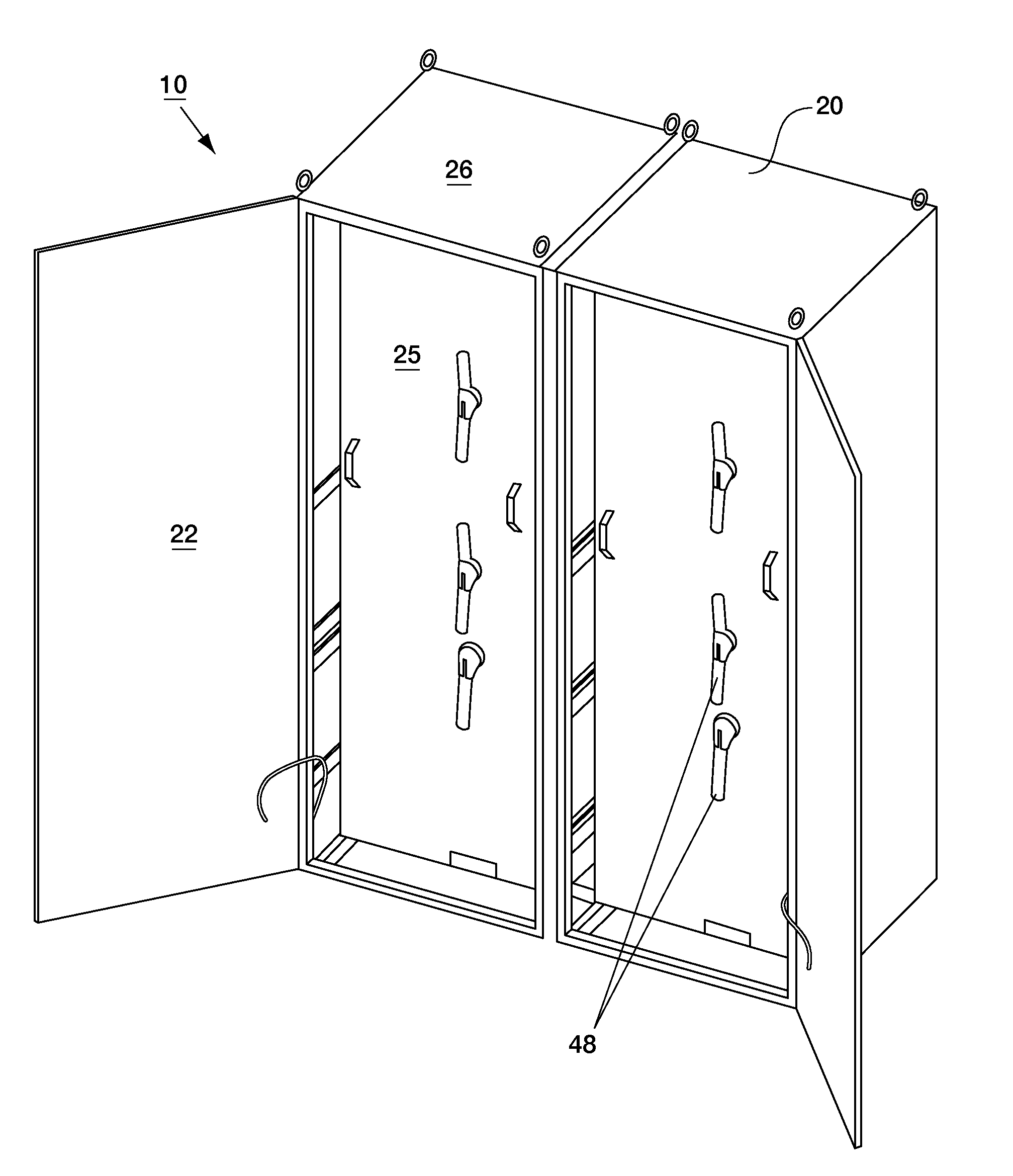
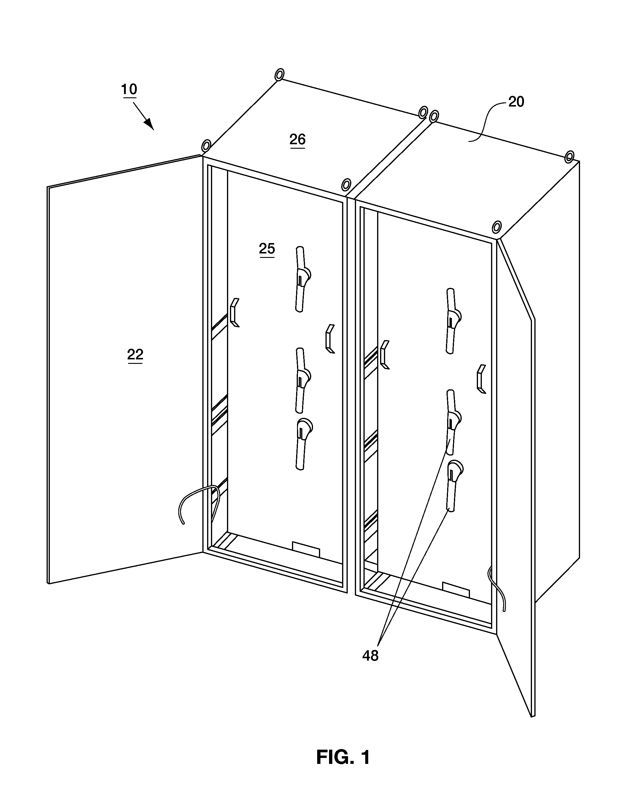
[0026]20—Cabinet;

[0027]22—Door;

[0028]24—Hinge;

[0029]25—Safety shield;

[0030]26—Housing;

[0031]30—Disconnect switch;

[0032]32—High voltage positive input bus bar;

[0033]34—High voltage positive output bus bar;

[0034]36—High voltage bus bar;

[0035]37—Ground bus bar

[0036]40—Disconnect assembly;

[0037]42—Linkage assembly;

[0038]43—Switch fitting;

[0039]44—Switch-to-switch arm;

[0040]46—Shaft;

[0041]48—Handle;

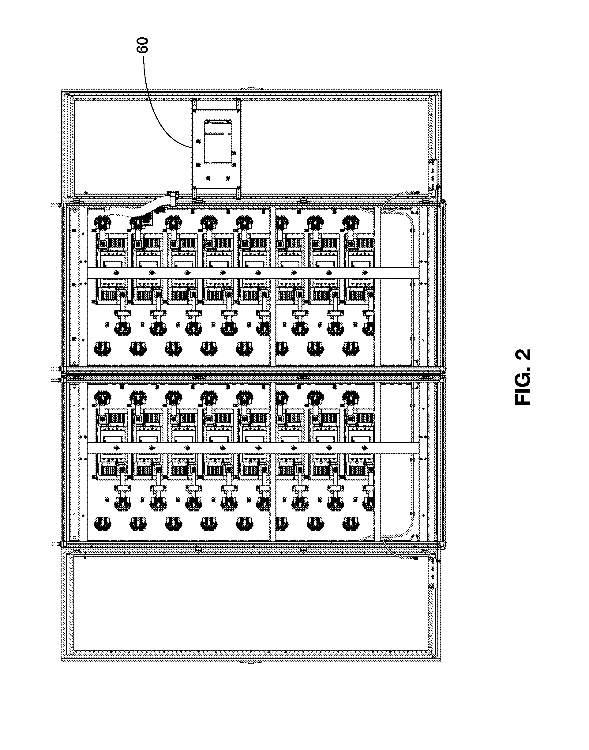
[0042]60—Control circuit board;

[0043]62—Power supply;

[0044]65—Current transducer (CT);

[0045]70—Antenna;

[0046]72—Receiver; and

[0047]74—Processor.

[0048]As shown in FIG. 1, disconnect system 10 is substantially maintained within cabinet 20 including housing 26 and doors 22. Doors 22 are closed during normal operation, but open to provide access to structures within housing 26. Rem...


PUM

PropertyMeasurementUnit
voltageaaaaaaaaaa
Electrically couplingaaaaaaaaaa
Electricallyaaaaaaaaaa

Abstract

A disconnect system for a solar installation shuts down power upstream from an inverter, so that it is safe for solar field personnel to perform work related to a solar installation. The system actuates multiple disconnect devices in one motion by a linkage assembly which can associate 2-4 disconnect switches with a single handle. This system preferably includes hardware and logic for monitoring the current and voltage output of electrically coupled combiner/recombiner boxes in the solar field, and for wirelessly transmitting this data to a user. A single disconnect cabinet can accommodate 2-20 inputs from associated recombiner boxes with 5 handles or less.

Description

CROSS-REFERENCE TO RELATED APPLICATIONS[0001]This application claims priority from the United States provisional patent application entitled DISCONNECT CABINET AND RECOMBINER BOX WITH WIRELESS MONITORING CAPABILITY, which was filed on May 3, 2013, and assigned the Ser. No. 61 / 818,940.[0002]This application is being filed concurrently with a United States utility application entitled MASTER RECOMBINER BOX WITH WIRELESS MONITORING CAPABILITY, which also claims priority from the provisional patent application entitled DISCONNECT CABINET AND RECOMBINER BOX WITH WIRELESS MONITORING CAPABILITY, which was filed on May 3, 2013, and assigned the Ser. No. 61 / 818,940. This co-pending application has a serial number of ______, and is hereby incorporated in its entirety.BACKGROUND[0003]1. Field[0004]The present invention relates generally to solar energy components, and more particularly, to a cabinet that disconnects power upstream from an inverter in a solar field, monitors the power output of...

Claims


Application Information

Patent Timeline
Patent Type & Authority Applications(United States)
IPC IPC(8): H01H47/00H01R43/00
CPCH01H47/002H01R43/00H01H71/1018H01H71/56Y10T29/49117H05K5/0004H05K5/0017
Inventor SOLON, DEAN
Owner SHOALS TECH GROUP
Why Eureka
Try Eureka