Water-jet operating head for cutting materials with a hydro-abrasive high pressure jet

Active Publication Date: 2014-11-06
BIESSE
View PDF15 Cites 7 Cited by
  • Summary
  • Abstract
  • Description
  • Claims
  • Application Information

AI Technical Summary

Benefits of technology

The present invention provides a water-jet operating head that allows for easy and quick replacement of parts subject to wear, and even in an automated manner, to reduce the time required for replacement and increase machine productivity. Additionally, the invention achieves this with a simple and relatively inexpensive structure. The head has a cylindrical body with a conical centering end to facilitate insertion of the nozzle-carrying support within the main support.

Problems solved by technology

A problem which is encountered in the operating heads of the above described type lies in the wear of the components inside the head through which the high pressure jet flows, as well as in the wear of some parts in which also the added abrasive flows.
This causes an enlargement of those passages, with a resulting decrease of effectiveness and precision in the cutting operation.
In this known solution, the operations for replacing the parts subject to wear and particularly the nozzle, are time-consuming, cumbersome and not adapted to be automated.

Method used


Image

  • Water-jet operating head for cutting materials with a hydro-abrasive high pressure jet
  • Water-jet operating head for cutting materials with a hydro-abrasive high pressure jet
  • Water-jet operating head for cutting materials with a hydro-abrasive high pressure jet

Examples


first embodiment

[0037]the invention is shown in FIG. 4 of the annexed drawings and can be used both in a three axis head and in a five axis head. In this figure, parts which are common to those of FIGS. 2 and 3 are designated by the same reference numerals. A first difference with respect to the case of FIGS. 2 and 3 lies in that the connecting element 16 is rigidly connected to the main portion 7A of the head. This of course applies to each connecting element in case there are provided two connecting elements which are diametrically opposite to each other.

[0038]In the illustrated example, the main portion 7A has a first element 71, defining the axial passage 8, and a second element 72, of tubular configuration, whose upper end is rigidly connected by an interference fit to the lower end portion of element 71. This arrangement is chosen only for simplifying the construction, while it is clearly understood that, in principle, the two elements 71, 72 could be made in a single piece and together defin...

second embodiment

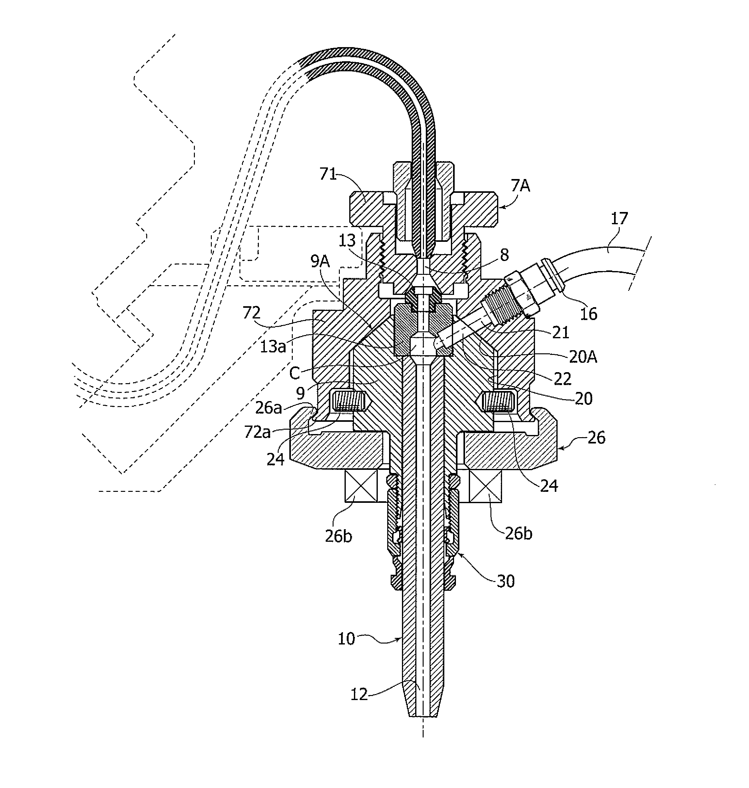
[0046]FIG. 5 shows the invention which, by way of example, is referred to the case of a five axis head. However, the construction of the head is absolutely identical to that of FIG. 4 (for which reason parts corresponding to those of FIG. 4 have been designated by the same reference numerals).

[0047]The only relevant difference with respect to the case of FIG. 4 lies in that in this case the cylindrical body of support 9 carrying the focusing nozzle 10 ends with the conical portion 9a which is received within a corresponding conical portion 20A of the cylindrical cavity 20 within which support 9 is slidably mounted. The function of conical portion 9A is to favor the center of cavity 20 at the time of insertion of support 9 within the element 72 of the main portion 7A of the head. For the rest, the head of FIG. 5 differs from that of FIG. 4 only for the configuration of its various elements, which however, are conceptually similar to those of FIG. 4. It is to be stressed in any case t...


PUM

PropertyMeasurementUnit
Angleaaaaaaaaaa

Abstract

A water-jet operating head for cutting materials by a high pressure hydro-abrasive jet includes a main portion which is to be carried by an operating machine movably along one or more axes and a focusing nozzle for ejecting the high pressure hydro-abrasive jet, carried by a support removably connected to the main portion of the head. This support also carries a primary nozzle with an orifice having a predetermined diameter arranged upstream of the focusing nozzle. The high pressure water jet is added with an abrasive agent which is fed through at least one connecting element at a mixing chamber interposed between the primary nozzle and the focusing nozzle. The connecting element is associated to the main portion of the head and the nozzle-carrying support is adapted to be slidably received within a cylindrical cavity of a main support forming part of the main portion of the head.

Description

TECHNICAL FIELD[0001]The present invention relates to water-jet operating heads using a high pressure hydro-abrasive jet, for cutting various materials, such as glass, stone, marble, metals, plastic materials, ceramic materials or in general any other material suitable to be worked by the above mentioned technology.BACKGROUND[0002]Operating heads of the above indicated type are to be used on machines in which the operating head is movable along one or more axes by means of electronically controlled motor means in order to perform cutting operations on pieces arranged on the machine table. In machines of this type the addition of the abrasive agent to the high pressure water jet enables cutting operations to be performed also on materials of medium and high hardness, and in general on all those materials for which cutting by a pure water jet is not possible.[0003]The invention relates to a water-jet operating head of the known type including:[0004]a head main portion, intended to be ...

Claims


Application Information

Patent Timeline
IPC IPC(8): B24C5/04B26F3/00B24C1/04
CPCB24C5/04B24C1/045B26F3/004Y10T29/4973
Inventor TRAINI, MATTEOBELLI, MARCO
Owner BIESSE
Why Eureka
Try Eureka