
Walking Stick with S-Shaped Flexure Mechanism to Store and Release Energy

a technology of flexure mechanism and walking stick, which is applied in the field of walking stick, can solve the problems of limited ability of standard walking stick, limited range of terrain conditions, and limitation of standard walking stick ferrule, and achieve the effects of reducing wasted energy, reducing discomfort, and increasing the ability of a person to walk

Active Publication Date: 2014-11-13
LAND FLYERS LLC
View PDF8 Cites 22 Cited by
  • Summary
  • Abstract
  • Description
  • Claims
  • Application Information

AI Technical Summary

Benefits of technology

The present invention is a walking stick that is designed to absorb energy in the downward motion of a walking stride and then release it in the final forward motion to aid in propelling the walker forward. It is designed to keep the walker in an ergonomically correct position, minimizing discomfort and reducing wasted energy. The walking stick is fashioned to be more aggressive and positively negotiate more complex terrains and surface conditions than current walking sticks. It has a hand grip that allows for more efficient transfer of force to the S-flexure spring, a foot that helps keep the user's leg away from the walking stick, and an S-flexure spring that mimics the flexibility of a human ankle and helps absorb and release forces. The walking stick also has an additional flex point in the foot that helps propel the walking stick forward to its next location.

Problems solved by technology

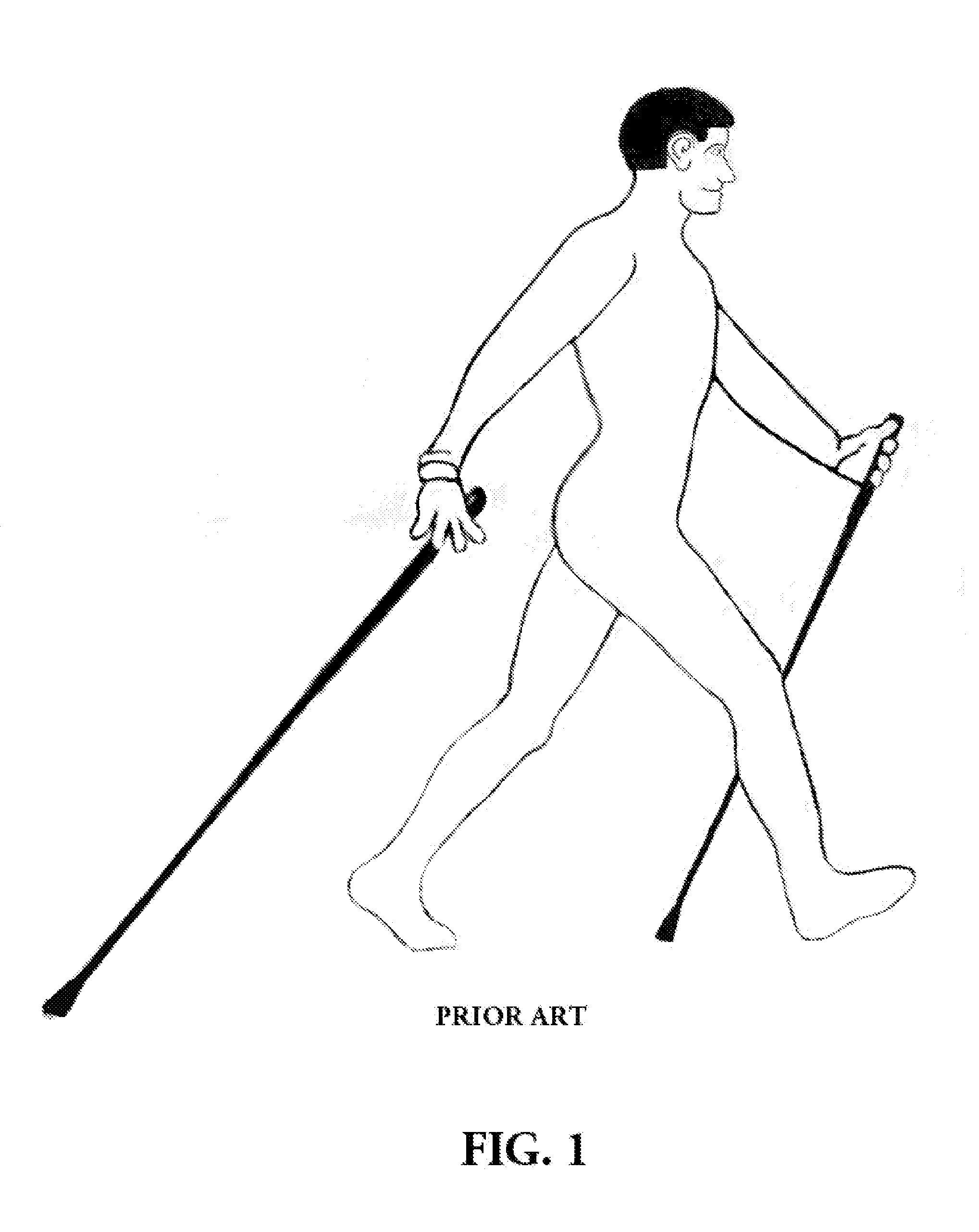
Standard walking sticks, hiking poles, and ski poles can only assist a person's capability to negotiate a limited number of landscapes and ground conditions.
Another limitation of the standard walking stick is the pointed tip of the ferrule.
This contributes to deterioration of the terrain surface as the pointed tip slices through and grabs into the surface.
It also causes the user to expend excess energy to remove the tip from the terrain surface and places transverse forces across the walking stick which contributes to walking stick failure (breakage).

Method used


Image

  • Walking Stick with S-Shaped Flexure Mechanism to Store and Release Energy
  • Walking Stick with S-Shaped Flexure Mechanism to Store and Release Energy
  • Walking Stick with S-Shaped Flexure Mechanism to Store and Release Energy

Examples


Embodiment Construction

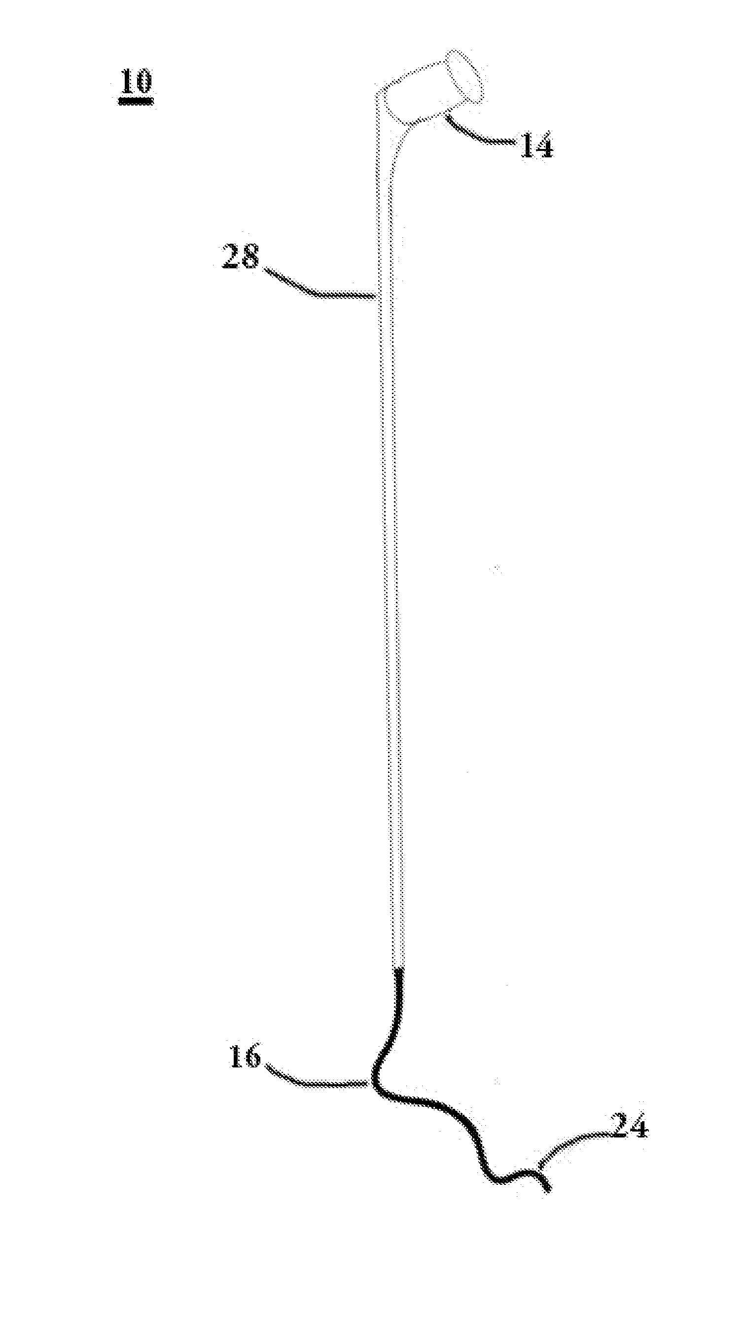
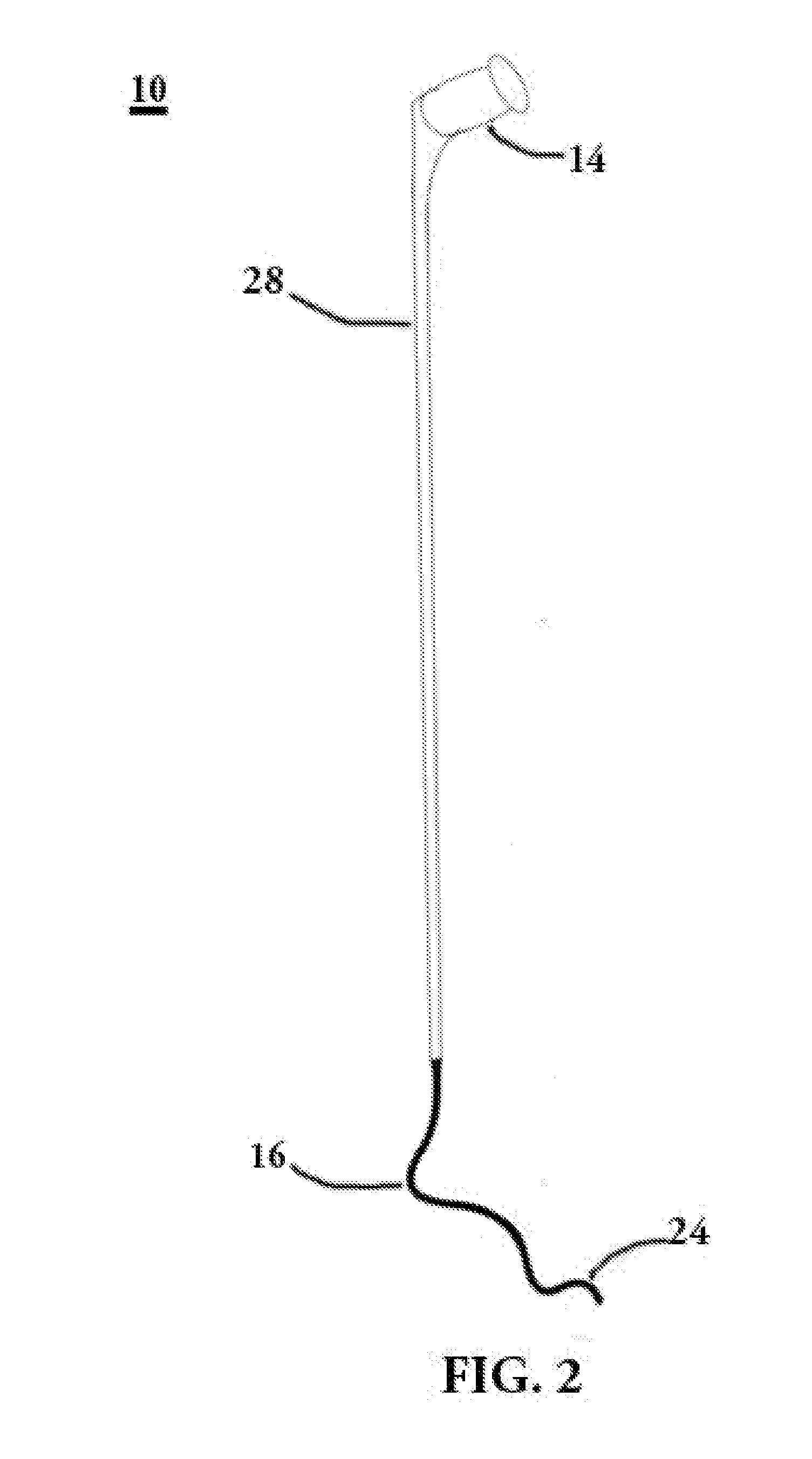
[0033]Referring to FIG. 2, therein is shown a preferred embodiment of the invention. This walking stick, generally designated by numeral 10, is molded as a single unit of fiberglass, carbon, aircraft aluminum, or other composite material. The appropriate material will be selected to achieve desired duty cycle and performance characteristics. Walking stick 10 includes a straight shaft 28 terminated at the upper end with a handgrip 14 and at the lower end with an S-flexure spring 16 and optionally a foot 24. Walking stick 10 may be constructed of ceramic, laminated linear fiberglass, aircraft aluminum, or other composite material. As those skilled in the art of extrusion molding are aware, the S-flexure spring 16, the foot 24, the straight shaft 28, and the handgrip 14 may be molded of laminated linear fiberglass as a single unit by adjusting the thickness and orientation of the premolded composite material at the appropriate positions along the length of the walking stick. In a prefe...


PUM


Abstract

A walking stick that takes inspiration from nature to absorb energy in the downward first motion of a walking stride and then return the stored energy to aid in propelling the walker forward in the final forward motion of the walking stride all the while keeping the walker in an ergonomically correct position which minimizes discomfort and reduces wasted energy. The walking stick that is the subject of this patent application utilizes a dual flexure spring configured in an S-shape (hereafter referred to as an S-flexure spring) as an extension of the straight shaft of the stick. The shape and location of the S-flexure spring are such that the spring force helps propel the walker forward.

Description

CROSS-REFERENCE TO RELATED PATENT APPLICATIONS[0001]Priority for this patent application is based upon provisional patent application 61 / 821,198 (filed on May 8, 2013). The disclosure of this United States patent application is hereby incorporated by reference into this specification.FIELD OF THE INVENTION[0002]The invention relates in general to mobility aid sticks and, more specifically, to a walking stick with a built in a dual flexure spring above the foot of the walking stick.BACKGROUND OF THE INVENTION[0003]Walkers, climbers, and other participants can benefit from walking sticks that have the feature of returning kinetic energy that is acquired as the walking stick compresses in contact with the ground. This retained energy has the benefit that the users have to expend less of their own energy moving their legs forward, thus allowing them to walk or climb further and faster more comfortably and with less fatigue. Experiencing this advantage, the user will increase their inter...

Claims


Application Information

Patent Timeline
Patent Type & Authority Applications(United States)
IPC IPC(8): A45B9/04
CPCA45B9/04A45B7/005A45B9/02A45B2009/007A45B2200/055A61H3/0288
Inventor RUDIN, NEAL H.
Owner LAND FLYERS LLC
Learn More