Supercharge Your Innovation With Domain-Expert AI Agents!

Braking Systems And Methods For A Winch Drum

a winch drum and braking system technology, applied in mechanical equipment, hoisting equipment, borehole/well accessories, etc., can solve the problems of operator breakage problems, difficulty in installing the drum band brake system, and significant difficulty in drum band brake system installation

Inactive Publication Date: 2014-11-13
SCHLUMBERGER TECH CORP
View PDF35 Cites 4 Cited by
  • Summary
  • Abstract
  • Description
  • Claims
  • Application Information

AI Technical Summary

Benefits of technology

The patent text describes a braking system for a winch drum that is used in drilling scenarios. The braking system is difficult to install and can cause breakage problems. The limited space between the braking system and the winch drum makes installation difficult, and operators often experience difficulty in adjusting the braking system to compensate for the space. The braking system also causes wear and tear on the brakes and can stick to the winch drum, leading to unreliable performance tests. The technical effects of the patent text are to provide a braking system for a winch drum that is easier to install, reduces breakage problems, and improves reliability.

Problems solved by technology

Thus, the limited space makes the drum band brake system installation significantly difficult, cumbersome and time consuming Additionally, operators often experience difficulty installing the drum band brake system because of the significant weight associated with the drum band brake system.
Further, operators often experience breakage problems when fixing the drum band brake system onto an adjustment thread rod associated with the winch drum.
Once manual adjustment of the brake lining is complete, the operators must verify the performance of brake lining of the drum band brake system by conducting performance tests of the brake lining and winch drum which are time consuming, costly and often unreliable.
Moreover, a brake lining of a drum band brake system, traditionally, is in the form of a band that is made of a flexible material which is often difficult to remove or separate from the winch drum when sticking occurs between surfaces of the brake lining and winch drum.

Method used


Image

  • Braking Systems And Methods For A Winch Drum
  • Braking Systems And Methods For A Winch Drum
  • Braking Systems And Methods For A Winch Drum

Examples


Embodiment Construction

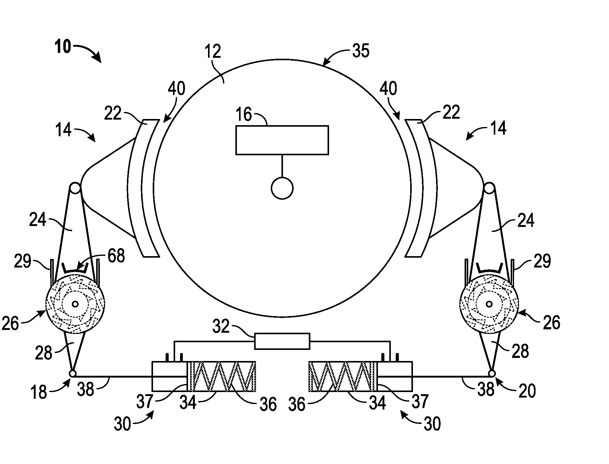
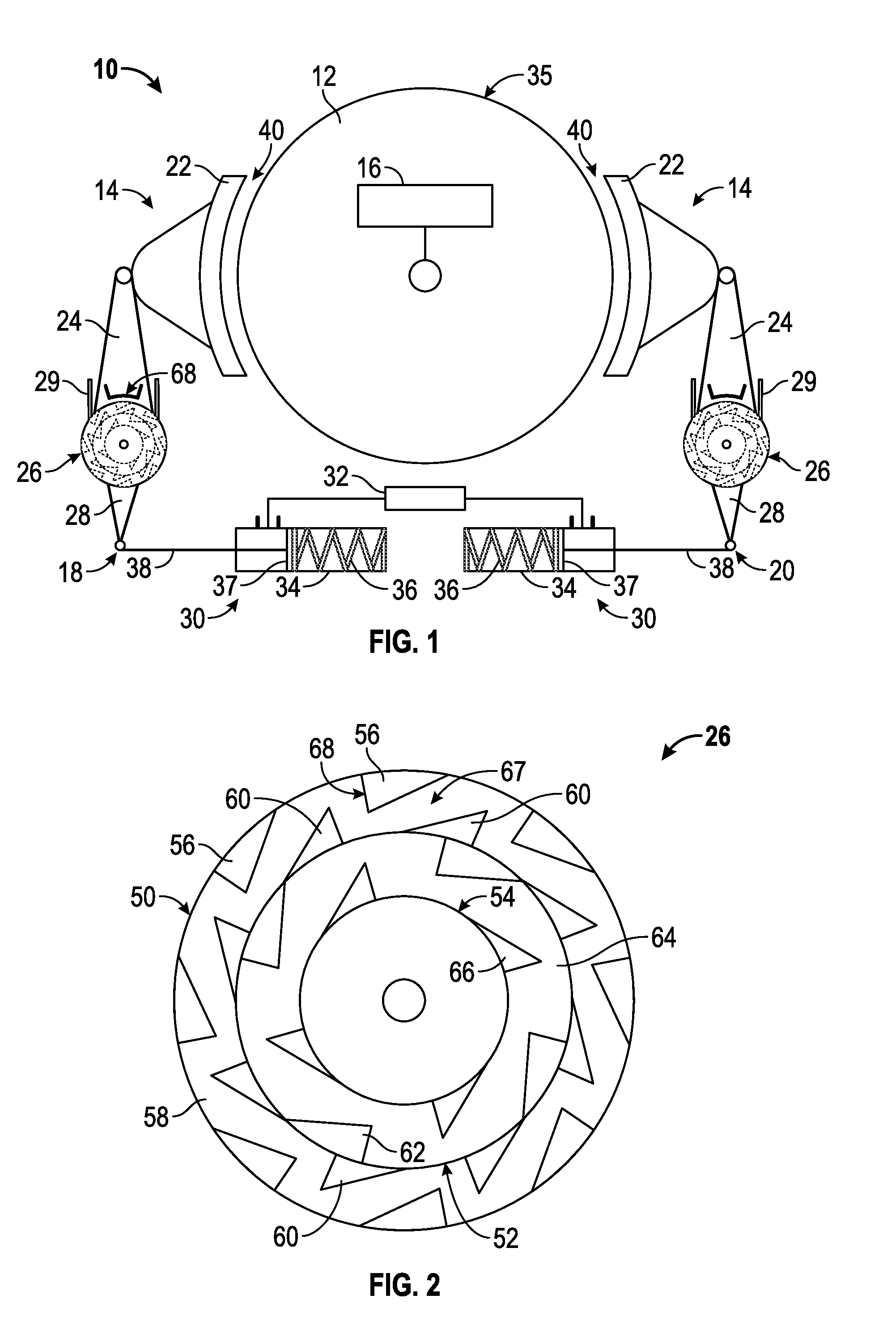
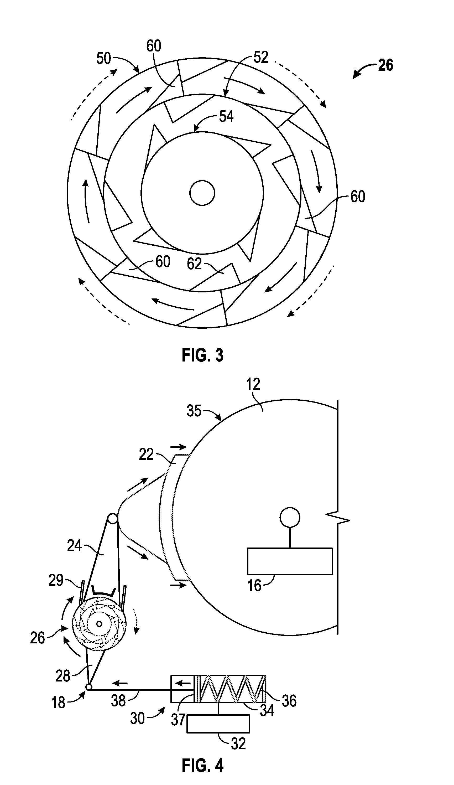
[0012]Referring now to the drawings wherein like numerals refer to like parts, FIG. 1 illustrates a winch drum system 10 which may have a winch drum 12 (hereinafter “drum 12”) and winch drum braking system 14 (hereinafter “braking system 14”) for the drum 12. A wire rope (not shown in FIGS. 1-7) may be attached and / or connected to the drum 12. In embodiments, the wire rope may be, for example, a wireline cable 802 (as shown in FIG. 8). The drum 12 may be sized and / or configured to receive and / or store an entire length of or at least a portion of the entire length of the wire rope. A power or energy source 16 (hereinafter “power source 16”) may provide mechanical power and / or energy to the drum 12 such that the drum 12 may be rotated in a clockwise direction and / or a counter-clockwise direction via the power source 16. The power source 16 may be, for example, a drum motor and / or the like. The drum 12 may release and / or retrieve the entire length or at least a portion of the entire le...


PUM


Abstract

Braking systems and methods are provided for a drum wench system having a winch drum having an outer surface and a winch drum braking system. The winch drum braking system has a first brake having a first brake lining, located adjacent to the winch drum, and a first three-ring ratchet linkage system connected to the first brake lining. The first three-ring ratchet linkage system is rotatable and adapted to move the first brake lining to a first position or a second position with respect to the outer surface of the winch drum. In the first position, the first brake lining contacts the outer surface of the winch drum to apply break force thereon, and, in the second position, the first brake lining is separated from the winch drum.

Description

FIELD OF THE INVENTION[0001]Aspects of the disclosure relate to wireline operations. More specifically, aspects relate to braking systems and methods for a winch drum that may be used in drilling scenarios.BACKGROUND OF THE DISCLOSURE[0002]Installation of a drum band brake system onto a winch drum requires the winch drum to be installed before subsequent installation of the drum band brake system. As a result of installing the winch drum prior to the drum band brake system, one or more operators (hereinafter “operators”) are required to complete the subsequent drum band brake system installation within a substantially limited space created by dimensions and structural features of the winch drum. Thus, the limited space makes the drum band brake system installation significantly difficult, cumbersome and time consuming Additionally, operators often experience difficulty installing the drum band brake system because of the significant weight associated with the drum band brake system....

Claims


Application Information

Patent Timeline
Patent Type & Authority Applications(United States)
IPC IPC(8): B66D5/08E21B19/084
CPCB66D5/08E21B19/084B66D5/26F16D49/16
Inventor ZHANG, KUNBREARD, STEPHANEJACQUEMONT, PIERRE
Owner SCHLUMBERGER TECH CORP
Features
  • R&D
  • Intellectual Property
  • Life Sciences
  • Materials
  • Tech Scout
  • Unparalleled Data Quality
  • Higher Quality Content
  • 60% Fewer Hallucinations
Learn More