Flat wiring member and method of manufacturing the same

a wiring member and flat technology, applied in the field of flat wiring members, can solve the problems of increased manufacturing cost, disadvantageous in terms of manufacturing cost, and difficulty in separating conductor wires from give positions, so as to prevent an increase in wiring resistance and reduce cost

Active Publication Date: 2014-11-13
HITACHI METALS LTD
View PDF14 Cites 17 Cited by
  • Summary
  • Abstract
  • Description
  • Claims
  • Application Information

AI Technical Summary

Benefits of technology

[0037]According to one embodiment of the invention, a flat wiring member can be provided that is thin but prevents an increase in wiring resistance due to a sufficient conductor cross sectional area, allows the branching of individual wires from any positions of a flat wire harness and allows the cost reduction of the flat wire harness, as well as a method of manufacturing the flat wiring member.

Problems solved by technology

However, since the conductive wires each formed of a solid wire are laid one by one on the upper surface of the lower insulating film so as to have a predetermined shape, it is disadvantageous in that the manufacturing cost increases with an increase in the number of wirings.
In addition, since plural conductive wires each formed of a solid wire are cover all together with the lower and upper insulating films, it is difficult to branch off the conductor wires from a give position of the flat harness.
The flat harness disclosed in JP-A-2002-203431 is advantageous in that the conductive wires can be branched off from a given position but it is disadvantageous in terms of the manufacturing cost because a step of joining the first and second flat cables is essentially required.
In addition, since the joint is located at the middle of the flat harness, it may be disadvantageous in terms of long-time reliability including weather resistance.
Here, when round enamel wires are bundled in a flat manner, it is considered disadvantageous in that the bundle of the enamel wires is likely to be separated due to external loads such as vibration since a joining area between adjacent enamel wires is small.
However, a resulting increase in thickness of the wire harness cannot be avoided and it is thus disadvantageous in that it is difficult to arrange in a narrow space (especially, in a thin gap).

Method used


Image

  • Flat wiring member and method of manufacturing the same
  • Flat wiring member and method of manufacturing the same
  • Flat wiring member and method of manufacturing the same

Examples


first embodiment

Flat Wiring Member

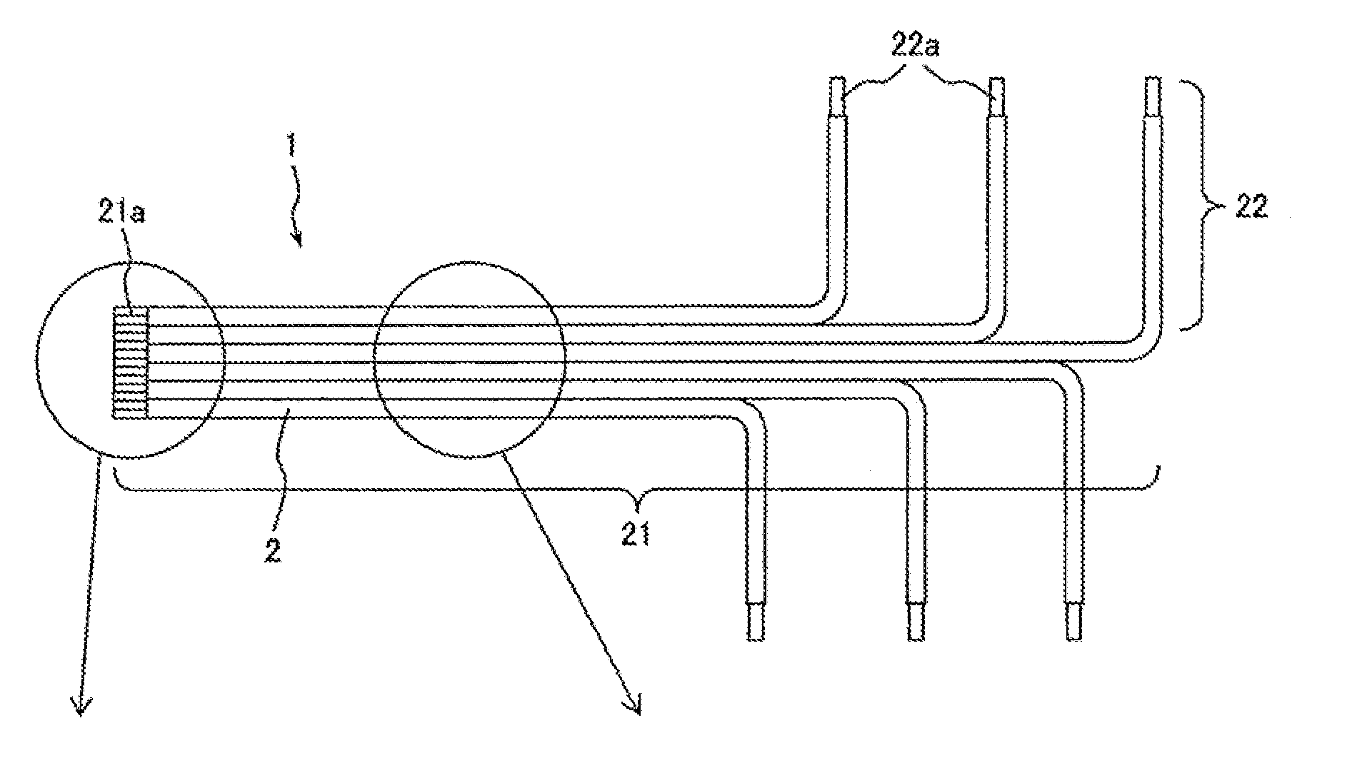
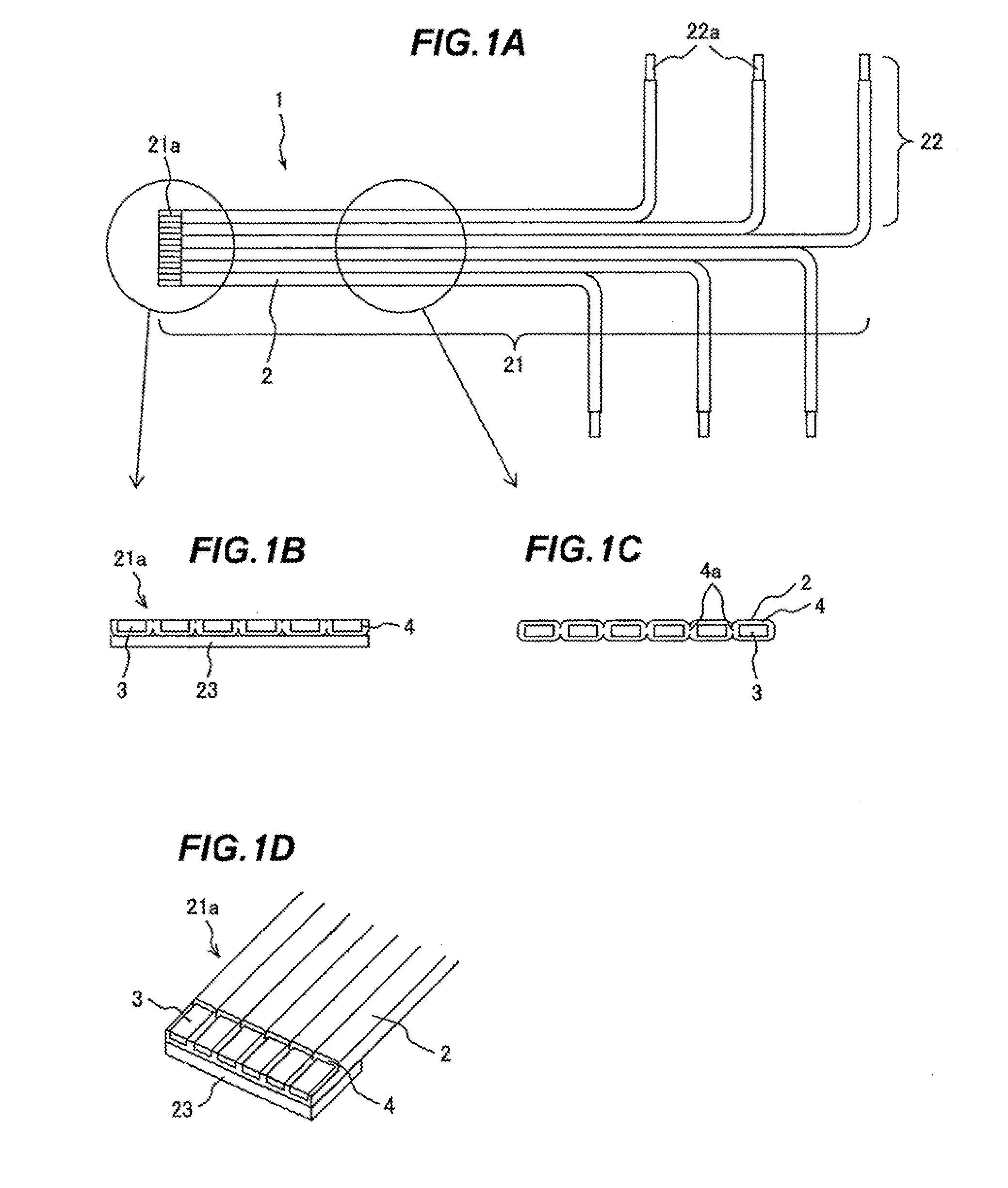
[0048]FIGS. 1A to 1D are schematic views showing an example of a flat wiring member in an embodiment of the invention. In detail, FIG. 1A is a front view of the entire flat wiring member 1, FIG. 1B is a cross sectional view of a terminal portion 21a of a wiring stem portion 21, FIG. 1C is a cross sectional view of the wiring stem portion 21, and FIG. 1D is a perspective view of the terminal portion 21a of the wiring stem portion 21.

[0049]As shown in FIGS. 1A to 1D, the flat wiring member 1 in the invention is formed by arranging plural rectangular enamel coated wires 2 in the form of a flat plate and has the wiring stem portion 21 and wiring branch portions 22. The wiring stem portion 21 is composed of the plural rectangular enamel coated wires 2 aligned in parallel to each other in which edge surfaces 4a of enamel coat layers 4 of the adjacent rectangular enamel coated wires 2 are adhered to each other, and each wiring branch portion 22 is formed by bending the re...

second embodiment

Flat Wiring Member

[0082]FIG. 8 is a schematic front view showing an example of a flat wiring member in the second embodiment. As shown in FIG. 8, a flat wiring member 1′ in the second embodiment is different from the first embodiment in that the wiring branch portions 22 extend over the wiring stem portion 21.

[0083]In the flat wiring member of the invention, each conductive wire is an enamel coated wire and electrical insulation between the conductive wires is thus ensured. Therefore, electrical short circuit does not occur even when the wiring stem portion 21 intersects with the wiring branch portions 22 as is in the flat wiring member 1′. Furthermore, since the rectangular enamel coated wire 2 is used as the conductive wire, an increase in a thickness at a crossover point is the minimum.

[0084]The flat wiring member 1′ demonstrates that branching position and direction of the wiring branch portion 22 from the wiring stem portion 21 can be arbitrarily determined. In other words, the...


PUM

PropertyMeasurementUnit
lengthaaaaaaaaaa
sizeaaaaaaaaaa
sizeaaaaaaaaaa

Abstract

A flat wiring member includes a plurality of rectangular enamel coated wires arranged in the form of a flat plate, a wiring stem portion that the rectangular enamel coated wires are arranged in parallel to each other and adjacent ones of the rectangular enamel coated wires are bonded to each other at a surface of an enamel coat layer thereof, and a wiring branch portion with the rectangular enamel coated wires bent so as to branch off from the wiring stem portion.

Description

[0001]The present application is based on Japanese patent application No. 2013-099896 filed on May 10, 2013, the entire contents of which are incorporated herein by reference.BACKGROUND OF THE INVENTION[0002]1. Field of the Invention[0003]The invention relates to a flat wiring member (or a flat wire harness or a flat harness) and, in particular, to a flat wiring member that is used for controlling a secondary battery module and is advantageous for increasing length and reducing the cost, as well as a method of manufacturing the flat wiring member.[0004]2. Description of the Related Art[0005]In recent years, secondary batteries typified by lithium-ion batteries and nickel-hydrogen batteries have been used more widely from portable electronic devices (e.g., mobile personal computers or cell-phones) to large electrical equipments (e.g., power sources for vehicles such as HEV (hybrid vehicle) or EV (electric vehicle), power storage sources, uninterruptible power-supply systems of data c...

Claims


Application Information

Patent Timeline
Patent Type & Authority Applications(United States)
IPC IPC(8): H02G3/02B21C37/15B21D7/14
CPCH02G3/02B21D7/14B21C37/155B21D7/022H01B13/0023H01B13/01254
Inventor TANAKA, KOTAROHORIKOSHI, TOSHIYUKISATO, TAKUMIMURAKAMI, KENICHIFUNAYAMA, YASUHIROOKAMOTO, ASUKA
Owner HITACHI METALS LTD
Why Eureka
Try Eureka