Remote monitoring systems

Inactive Publication Date: 2014-11-13
ILLINOIS TOOL WORKS INC
View PDF8 Cites 57 Cited by
  • Summary
  • Abstract
  • Description
  • Claims
  • Application Information

AI Technical Summary

Benefits of technology

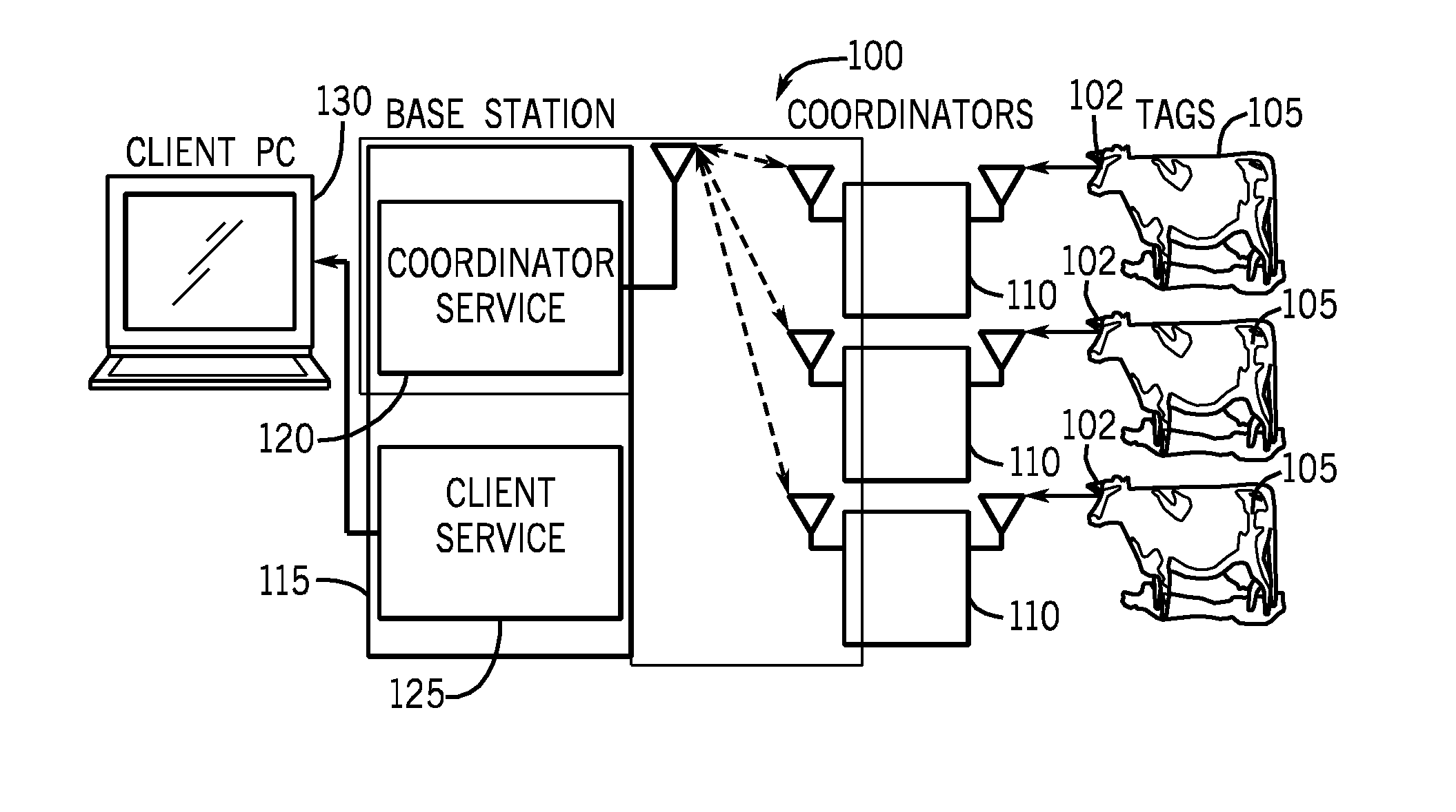
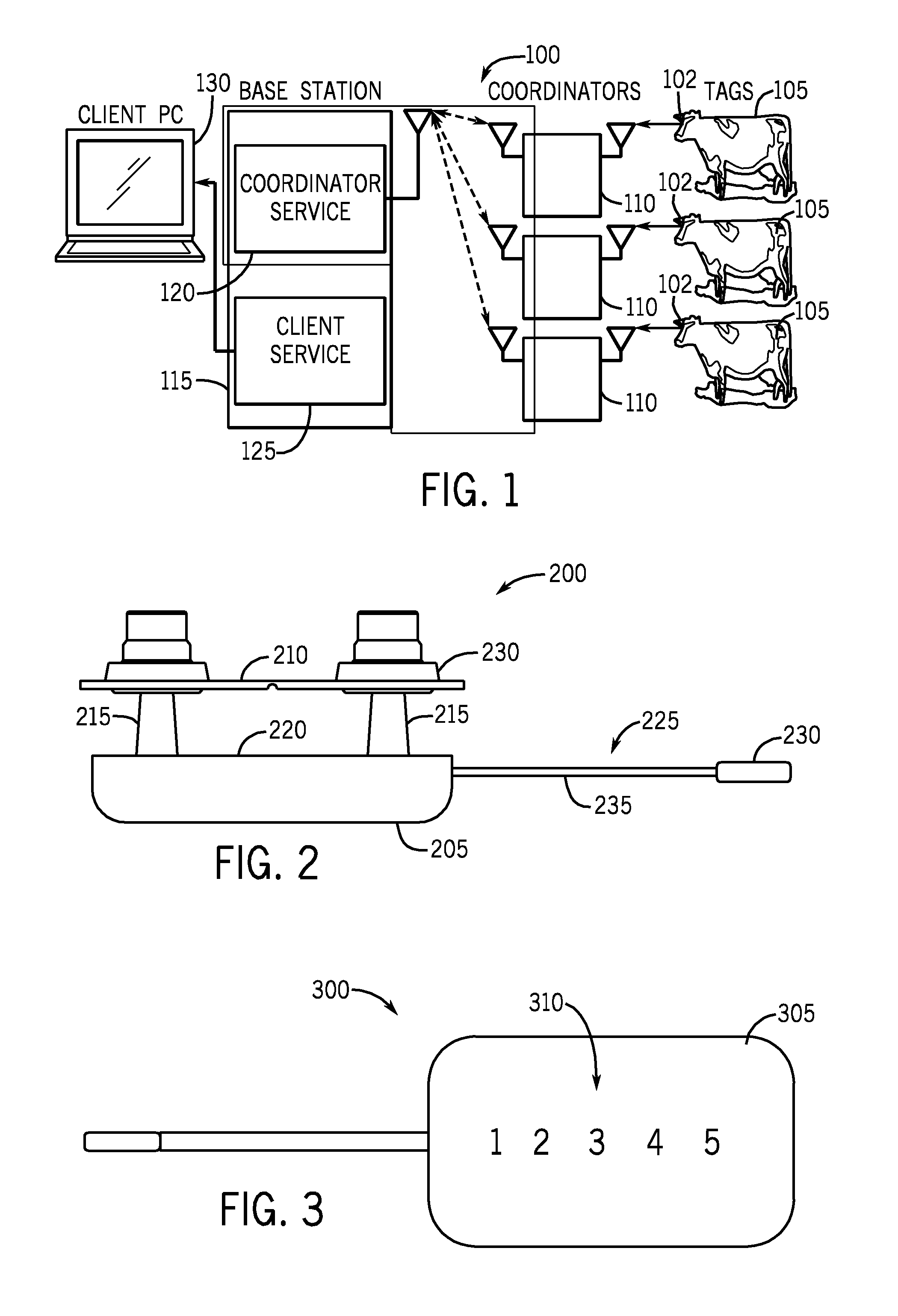
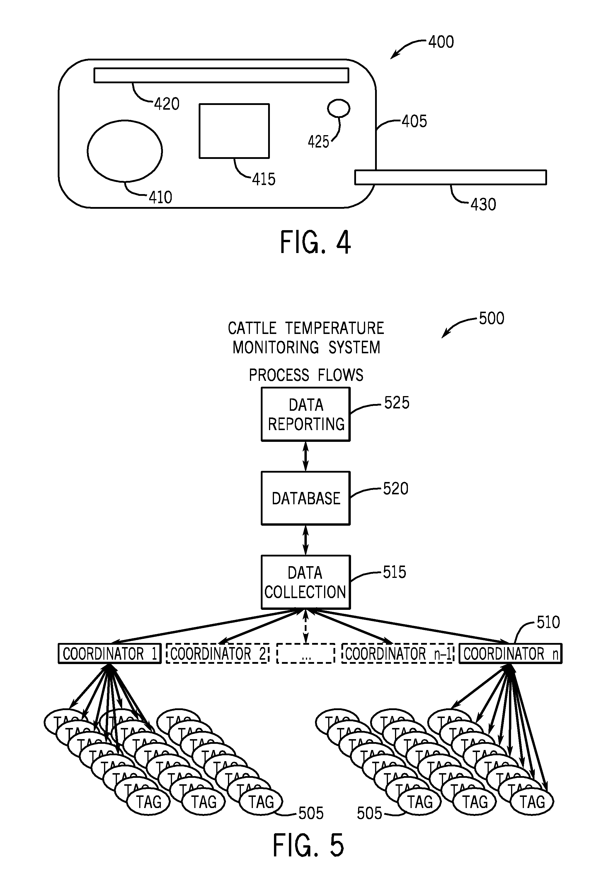
[0019]In some embodiments, the present invention provides systems comprising: a plurality of sensors configured to transmit data on a low power and/or short range transmission link; one or more coordinators in wireless communication with the sensors, the coordinators configured to convert signals received via the low power and/or short range transmission link to a longer range transmission link; and a base station in wireless communication with the one or more coordinators via the longer range transmission link so that data generated by the sensors is transferred to the base station via the coordinators. In some embodiments, the low power and/or short range transmission link utilizes a 802.15.4 signal. In some embodiments, the longer range link is selected from the group consisting of a cellular network and a transmission link using a 802.11 protocol. In some embodiments, the system is configured so that only one sensor is transmitting data to the coordinator at any given time. In some embodiments, the sensor is selected from the group consisting of time sensors, temperature sensors, humidity sensors, magnetic field sensors, voltage sensors, current sensors, noise sensors, pressure sensors, electrical switches, biological sensors, pH sensors, motion sensors, chemical sensors, pathogen sensors, bacteria sensors, strain gauges, ultra violet sensors, proximity sensors, flow rate sensors, gas sensors, imaging devices, accelerometers, and gyroscopes.
[0020]In some embodiments, the present invention provides systems comprising: a plurality of tags affixable to an animal, the tags configured to transmit data to a coordinator on a low power and/or short range transmission link; one or more coordinators in wireless communication with the tags, the coordinators configured to convert signals received via the low power and/or short range transmission link to a longer range transmission link; and a base station in wireless communication with the one or more repeater stations via the longer range transmission link so that data generated by the tags is transferred to the base station via the coordinators. In some embodiments, the low power and/or short range transmission link utilizes a 802.15.4 protocol. In some embodiments, the longer ran

Problems solved by technology

Consequently, many problems arose, but in particular related to health and fertility.
A common problem with these systems is the difficulty in monitoring large herds and also great inconsistencies when monitoring is based on human observation.
These systems suffer several general drawbacks.
First, data transmission from the systems is unre

Method used


Image

  • Remote monitoring systems
  • Remote monitoring systems
  • Remote monitoring systems

Examples


example 1

[0064]The tympanic temperature tags of the present invention were field tested and compared to vaginal temperature measurement. Briefly, tags (approximately 24) were installed into cow's ears to collect temperature data for approximately 1 month. A predetermined number of tags (8) were removed after 8 days to compare the readings from the tympanic temperature with a vaginal core body temperature using a Hobo device. The remaining tags were left in for additional observations. The following observations were made: ambient temperatures were collected, algorithms for use in measuring temperature for sickness were developed, irritation from thermister was assessed, behavior from the weight of the tags was assessed, and retention of the tags was assessed.

[0065]The thermister was small enough to enter the cow's ear canal without any apparent problems. Pulling on the ear away from the animal allowed the ear canal to open up and the thermister was easily inserted into the ear canal. Once th...

example 2

[0068]In a separate trial, cow tag number 16 exhibited from the very beginning of the trial possible illness based on the large temperature swings. For the first two days, temperature recordings show significant swings in the core body temperature of + / −2.0 degrees F. through the course of the day. Based on this observation and prior testing, this is an indication of possible illness on the animal. After consulting with the veterinarian, the initial temperature changes were caused by a side effect of sweating from a vaccine which was administered during the installation of the core body temperature tag. However, on day three a significant temperature spike continued. On day four, the veterinarian pulled the animal from the pen and the animal was diagnosed with BRD (Bovine Respiratory Disease) and treated. The temperature swing continued through the next day and then steadily got smaller on day 6-7.

example 3

[0069]In the same trial as Example 2, cow tag number 18 exhibited from the very beginning of the trial possible illness based on the large temperature swings. The initial temperature changes were attributed to vaccination. On the fourth day, a large swing in core body temperature was detected which is indicative of a possible illness. The next day that day the animal was pulled from its pen, diagnosed with BRD (Bovine Respiratory Disease), and treated.


PUM


Abstract

A system includes sensors for transmitting data on a low power and/or short range transmission link, and one or more coordinators in wireless communication with the sensors. The coordinators convert signals received via the low power and/or short range transmission link to a longer range transmission link. A base station is in wireless communication with the coordinators via the longer range transmission link so that data generated by the sensors is transferred to the base station via the coordinators.

Description

[0001]This application claims the benefit of U.S. Provisional Application 61 / 565,357, filed Nov. 30, 2011, the entire contents of which are incorporated herein by reference.FIELD OF THE INVENTION[0002]The present invention provides systems for remotely monitoring sensors, particularly systems for remotely monitoring the temperature of subject animals.BACKGROUND OF THE INVENTION[0003]During the last 25 years many Western countries have witnessed substantial changes in the roles of veterinarians working in dairy cattle practice. Until the 1970s, the emphasis of their work was on the treatment of individual, clinically diseased animals, and it was only when the farmer decided a particular cow needed attention that he would call out his practitioner—it was an era of passive veterinary attention.[0004]In the early 1970s, however, things began to change. Herd fertility schemes were introduced, first in the UK and Australia, and shortly afterwards in other Western countries. They represent...

Claims


Application Information

Patent Timeline
IPC IPC(8): A01K29/00G01K1/02G01K13/00
CPCA01K29/005G01K13/004G01K1/024A01K11/006A61B5/0008A61B5/002A61B5/1112A61B5/145A61B5/6817A61B2503/40A61B2560/0209A61D17/002G01K1/026G01K13/20G01K13/223
Inventor DOWNING, MARK L.PLIML, ROBERT L.SPELBRING, STEVEN S.JOHNSON, NATHAN W.CANNON, KIMBERLY A.DINA, DANIEL
Owner ILLINOIS TOOL WORKS INC
Why Eureka
Try Eureka