Antenna arrangement and device

Active Publication Date: 2014-11-13
PERLOSGUANGZHOU ELECTRONICS COMPONENTS
View PDF6 Cites 16 Cited by
  • Summary
  • Abstract
  • Description
  • Claims
  • Application Information

AI Technical Summary

Benefits of technology

[0008]The invention may also provide the advantage that the antenna is implemented in a space-saving way in an electronic

Problems solved by technology

A problem with this is that conventional antenna arrangements cannot cover esp

Method used


Image

  • Antenna arrangement and device
  • Antenna arrangement and device
  • Antenna arrangement and device

Examples


Example

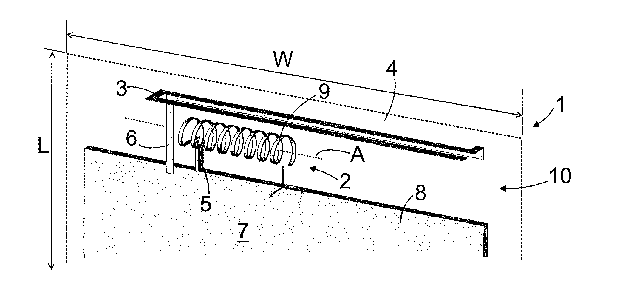
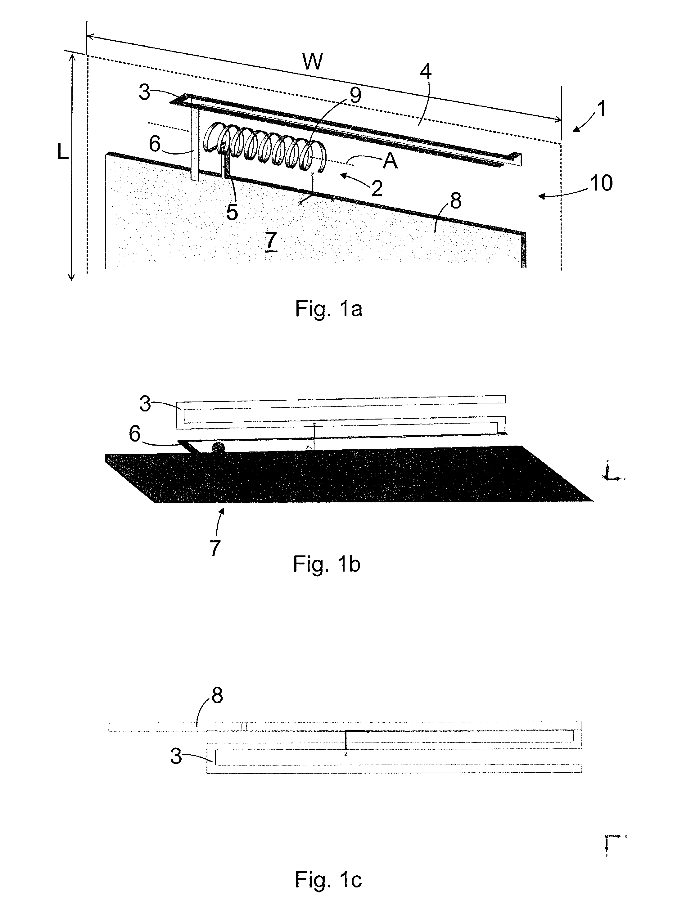
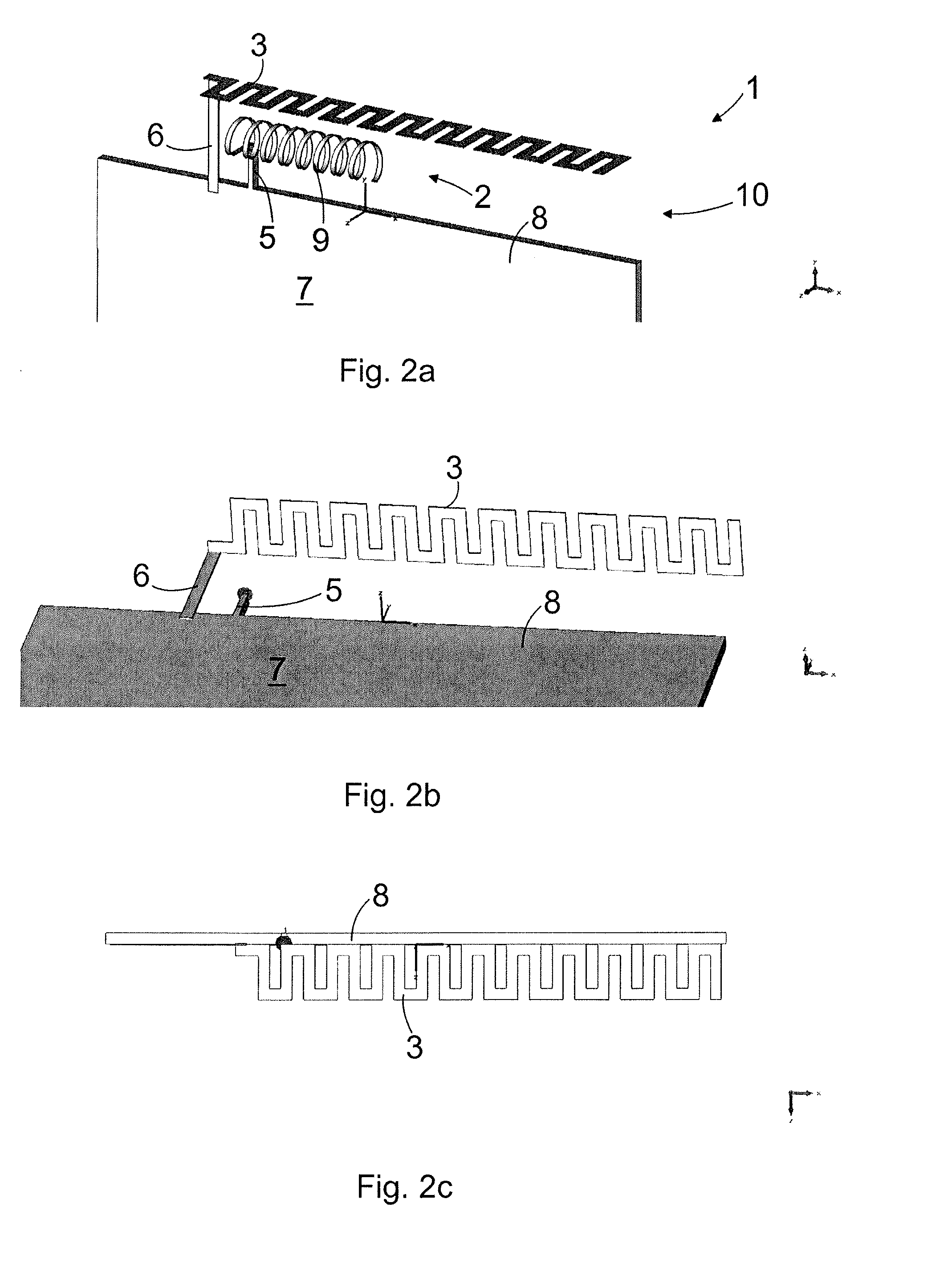
[0043]FIG. 1a is a schematic perspective view, FIG. 1b is another schematic perspective view, and FIG. 1c is a schematic side view of an example antenna arrangement and electronic device.

[0044]The antenna arrangement 1 is a part of an electronic device 4 that is depicted by dash line in FIG. 1a.

[0045]The electronic device 4 may be a mobile phone, some other portable or fixedly positioned communication means that functions at least partially wirelessly, such as a communicator, or some other portable electronic device, such as a palmtop computer, portable computer, game console or controller, playback device for audio and / or visual material, pulse counter, code reader, transmitter and / or receiver intended for measuring purposes and functioning wirelessly, or the like.

[0046]The antenna arrangement 1 constructs an antenna 10 that comprises two radiator elements, that is a first radiator element 2 and a second radiator element 3. It is to be noted, however, that the antenna arrangement ...


PUM


Abstract

An antenna arrangement of an electronic device and a device is disclosed. The antenna arrangement includes two radiator elements. The first radiator element of the two radiator elements is connected to a feed element. A second radiator element of the two radiator elements is a passive element and connected to a ground plane. The first radiator element is arranged to feed the second radiator element by radiating energy.

Description

BACKGROUND[0001]The invention relates to an antenna arrangement comprising two radiator elements.[0002]The invention further relates to an electronic device, comprising at least two radiator elements.[0003]The demand for wireless communication using multiple frequency bands increases all the time.[0004]A problem with this is that conventional antenna arrangements cannot cover especially low frequency bands without use of active components such as switches.BRIEF DESCRIPTION[0005]Viewed from a first aspect, there can be provided an antenna arrangement comprising a first radiator element of said two radiator elements connected to a feed element, a second radiator element of said two radiator elements being a passive element and connected to a ground plane, the first radiator element arranged to feed the second radiator element by radiating energy.[0006]Thereby a simple antenna arrangement having ability to cover low frequency bands may be achieved.[0007]Viewed from a further aspect, th...

Claims


Application Information

Patent Timeline
IPC IPC(8): H01Q5/00H01Q21/00H01Q1/36H01Q5/10
CPCH01Q5/0062H01Q1/362H01Q21/00H01Q1/243H01Q1/36H01Q9/42H01Q5/25H01Q5/378H01Q5/40H01Q5/385H01Q5/30H01Q7/04H01Q9/0414
Inventor BASIRAT, PARVIZ
Owner PERLOSGUANGZHOU ELECTRONICS COMPONENTS
Why Eureka
Try Eureka