Method of Enhanced Depth Image Acquisition

a depth image and depth image technology, applied in the field of enhanced depth image acquisition, can solve the problems of increasing the cost and complexity of the image acquisition system overall, affecting the resolution of current commercially available devices, and requiring a large amount of laborious calibration, so as to reduce the noise of tof cameras, improve the depth image acquisition procedure, and optimise the depth image formation

Inactive Publication Date: 2014-11-13
TECHN UNIV MUNCHEN FORSCHUNGSFORDERUNG & TECHTRANSFER
View PDF5 Cites 40 Cited by
  • Summary
  • Abstract
  • Description
  • Claims
  • Application Information

AI Technical Summary

Benefits of technology

[0010]In general, the present invention resides in a novel method to acquire depth images, based on combining at least two ToF cameras. The present invention modifies the depth image acquisition procedure by actively controlling the lighting of an object such that the at least two cameras emit and measure the reflected light in different lighting states. Assuming the scene is static during these three stages and gathering the obtained depth measurements in each lighting state, a set of constraints is established that should hold in every step and may be used to optimise the depth images formed by each camera. The ToF configuration of the present invention advantageously reduces the noise of ToF cameras and enables the production of smooth and accurate depth value estimates of the observed scene. The only hardware requirements of the present invention are access to the control of the lights of the two cameras and that the ToF cameras use the same light wavelength and no synchronisation of the two cameras is required.
[0011]The method of the invention relies on a calibrated ToF configuration, as illustrated in FIG. 1 and on an active control of the lighting of the object. According to the invention, the lighting is controlled by turning the lighting of the each of the cameras on and off alternately. Depth measurements are determined in each state. The depth images in each camera may then be optimised both overall and per pixel based on the measurements determined during the different lighting stages and using the geometrical constraints of the set-up according to the invention. In contrast to the prior art, the present invention improves ToF depth images using changing lighting conditions and multiple views. In addition, the present invention is able to use the interference generated from light signals emitted simultaneously from different cameras using the same modulation frequency.

Problems solved by technology

However, current commercially available devices have a low resolution and are affected by several sources of errors such as noise, systematic wiggling error, reflectivity / integration time error and flying pixels.
The drawback of such approaches is that they mostly rely at some level on putting in correspondence point clouds derived from the depth images.
All of these approaches involve a large amount of laborious calibration.
This clearly increases the costs and complexity of the image acquisition system overall.
These methods are conducted posterior to the image acquisition and are also complex, involving a large amount of processing.
However, the accuracy is improved at the significant cost of generally slow optimisations.

Method used


Image

  • Method of Enhanced Depth Image Acquisition
  • Method of Enhanced Depth Image Acquisition
  • Method of Enhanced Depth Image Acquisition

Examples


Embodiment Construction

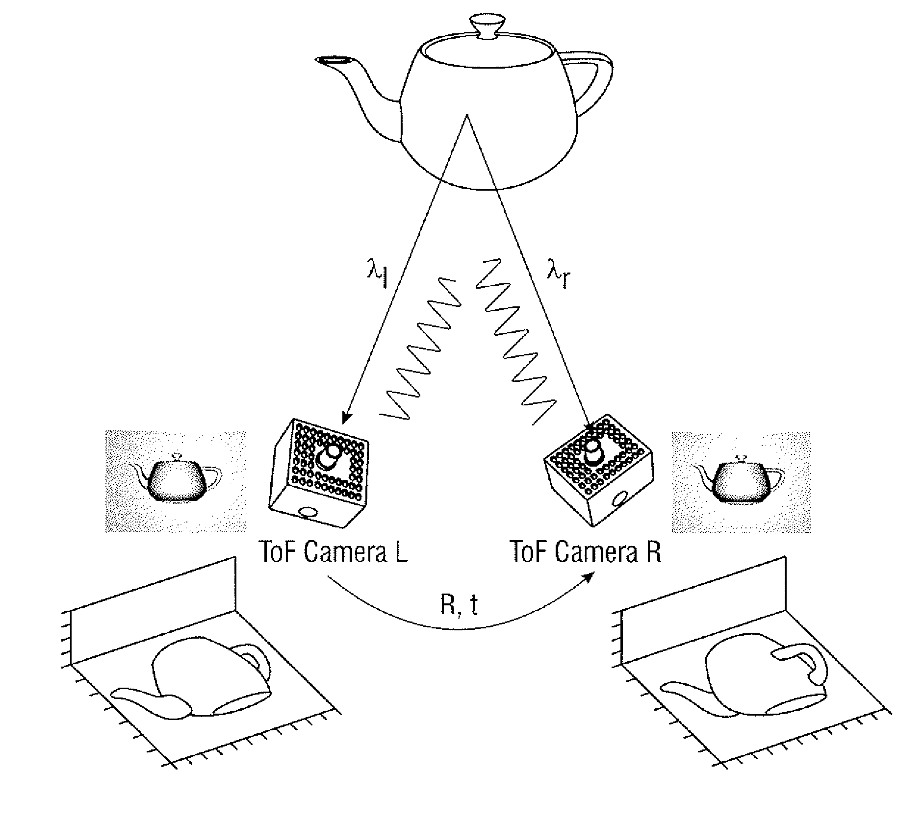
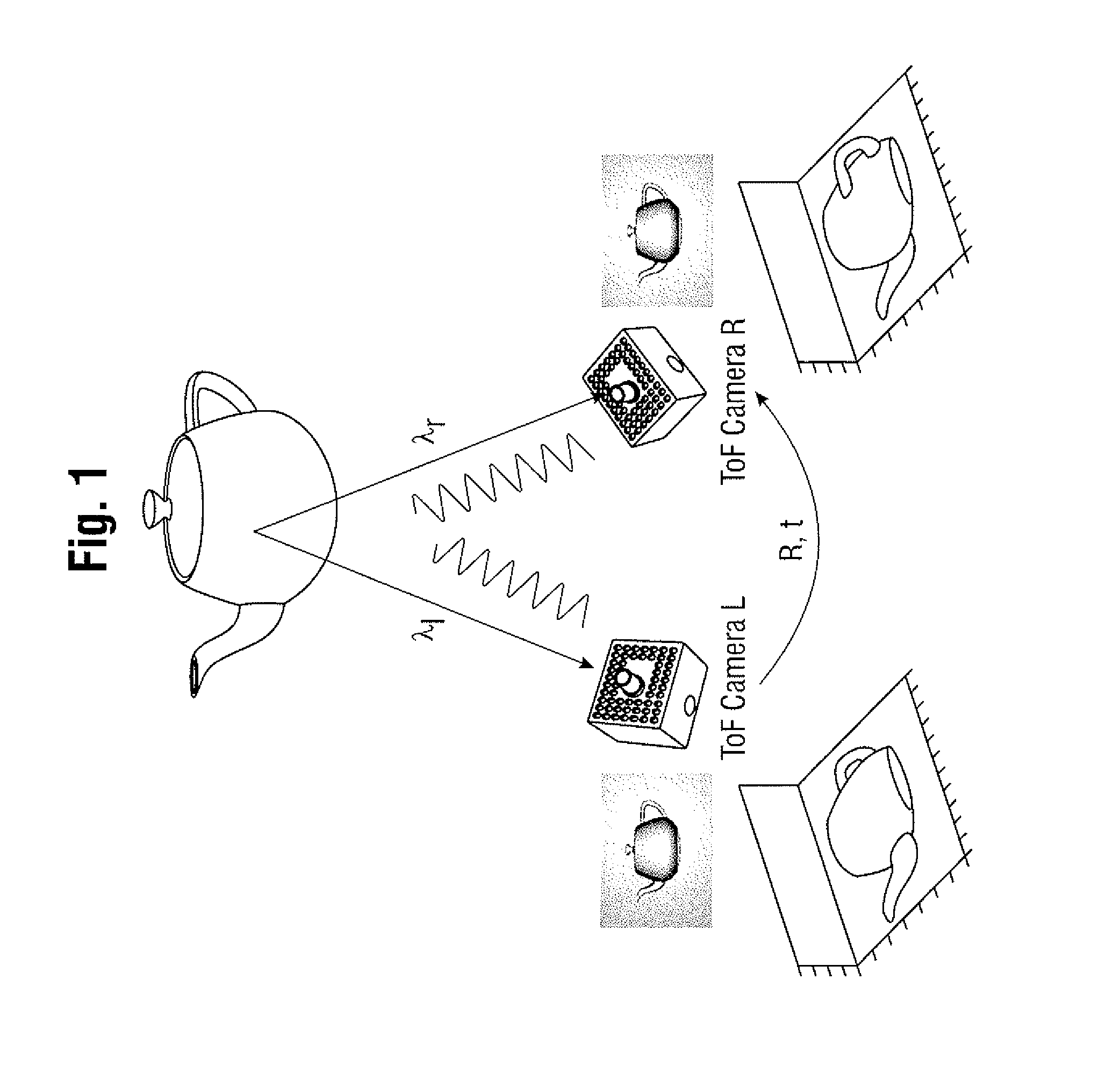
Monocular ToF Camera

[0019]The present invention is based on a known mechanism used by individual ToF cameras to recover the depth images.

[0020]To facilitate the measurement of the traveled time (or the time of flight), the intensity of the emitted light is modulated with a sinusoidal signal. With the right choice of modulating frequency, the traveled time required to estimate the distance is directly and unambiguously recovered from the phase shift between the emitted and received signals.

[0021]The emitted g(t) and the received signal S(t) may be expressed as sinusoidals of the form:

g(t)=A·cos(ω·t)+B,  (1)

S(t)=A′·cos(ω·t+φ)+B′,  (2)

where A represents the amplitude and B the offset of the emitted signal (respectively A′ and B′ for the received signal), ω is the modulation frequency in radians per second, and φ is the phase shift of the received signal with respect to the emitted signal.

[0022]The depth measurement for each pixel of the CMOS / CCD sensor is found by measuring the phase s...


PUM


Abstract

The present invention provides a method and apparatus for depth image acquisition of an object wherein at least two time-of-flight cameras are provided and the object is illuminated with a plurality of different light emission states by emitting light signals from each camera. Measurements of the light reflected by the object during each light emission state are obtained at all the cameras wherein the measurements may then be used to optimise the depth images at each of the cameras.

Description

CROSS-REFERENCE TO RELATED APPLICATIONS[0001]This application claims priority from PCT / EP2012 / 052339 filed on Feb. 10, 2012 and from EP 11154039.9 filed on Feb. 10, 2011 both of which are hereby incorporated by reference in their entireties.BACKGROUND[0002]Time of Flight (ToF) cameras are active range sensors that provide depth images at high frame-rates. They are equipped with a light source, normally infrared, that illuminates an object, for example a human body, or surface which may comprise different materials, wherein the object or surface may be part of a scene, and a CMOS / CCD (Charge-Coupled Device) sensor, as in a standard camera, that captures the reflected infrared light. The distance to the objects in the observed scene is measured based on the time of flight principle, that is, the distance is proportional to the time spent by the signal to reach the surface of an object and come back.[0003]Depth measurements may in this way obtained for each pixel of the CMOS / CCD sensor...

Claims


Application Information

Patent Timeline
Patent Type & Authority Applications(United States)
IPC IPC(8): H04N13/02G01S17/87G01S17/894
CPCH04N13/0271G01S7/497G01S17/87G01S17/003H04N13/271G01S17/894
Inventor NAVAB, NASSIRCASTANEDA ZEMAN, VICTOR ANTONIOMATEUS, DIANA
Owner TECHN UNIV MUNCHEN FORSCHUNGSFORDERUNG & TECHTRANSFER
Why Eureka
Try Eureka