
System and method for detecting, tracking and estimating the speed of vehicles from a mobile platform

a mobile platform and vehicle speed technology, applied in the field of camera-based analysis of road traffic, can solve the problem that algorithms do not detect moving objects directly

Active Publication Date: 2014-11-13
CONDUENT BUSINESS SERVICES LLC
View PDF10 Cites 194 Cited by
  • Summary
  • Abstract
  • Description
  • Claims
  • Application Information

AI Technical Summary

Benefits of technology

The patent describes a system and method for measuring the speed of vehicles on the ground using a movable platform with a camera and monitoring equipment. The camera detects and tracks vehicles on a road, even as the platform moves. The system measures the speed of the target vehicle by keeping it in view. The technology allows for the capture of license plate images with a telephoto lens. The technical effect is a more accurate and efficient method for measuring vehicle speed.

Problems solved by technology

An existing issue is to detect a moving vehicle, measure its speed, and track the vehicle to capture an image of the vehicle's license plate.
These algorithms do not detect moving objects directly.

Method used


Image

  • System and method for detecting, tracking and estimating the speed of vehicles from a mobile platform
  • System and method for detecting, tracking and estimating the speed of vehicles from a mobile platform
  • System and method for detecting, tracking and estimating the speed of vehicles from a mobile platform

Examples


Embodiment Construction

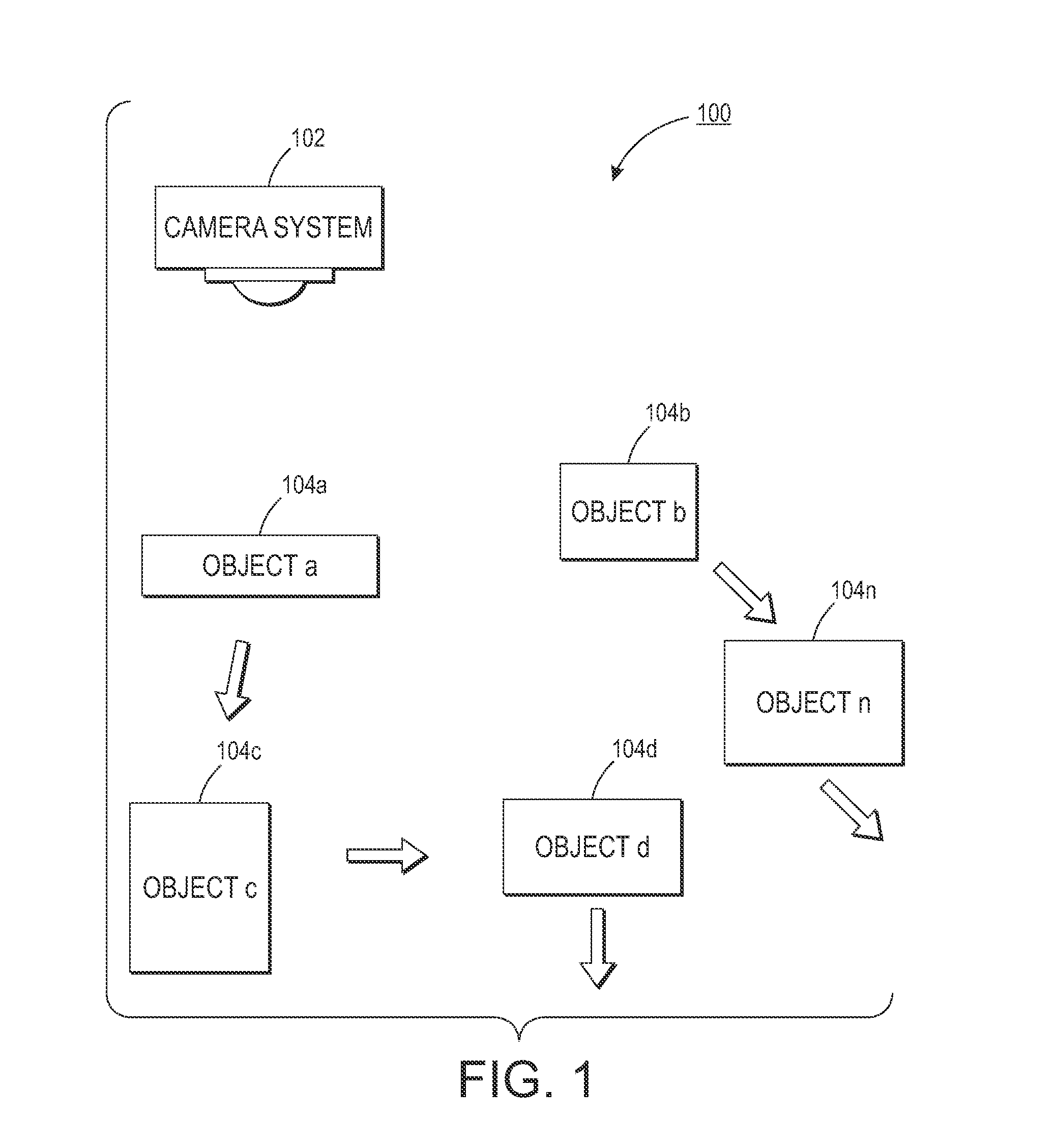
[0031]FIG. 1 is a block diagram 100 illustrating an environment in which the present concepts may be employed. A camera system 102 is positioned to monitor rigid and semi-rigid objects 104a-104n. The arrows associated with each of the objects 104a-104n represent different motions or movements of the objects 104a-104n. It is also to be understood that in the following discussion, a semi-rigid object is understood to be equivalent to a configuration of point locations that undergo a similarity transform, with some deviation on the locations.

[0032]In alternative environments, the camera system 102 may be in a stationary location or may be designed to be mobile. In the stationary embodiment the camera system will pivot and / or pan from the stationary position. Examples of stationary camera systems include security camera arrangements found in offices, stores, banks among other locations. A moving camera arrangement may be found on moving vehicles such as automobiles, trucks, airplanes, h...


PUM


Abstract

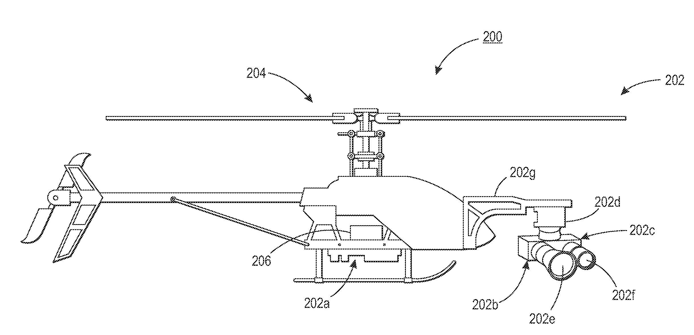
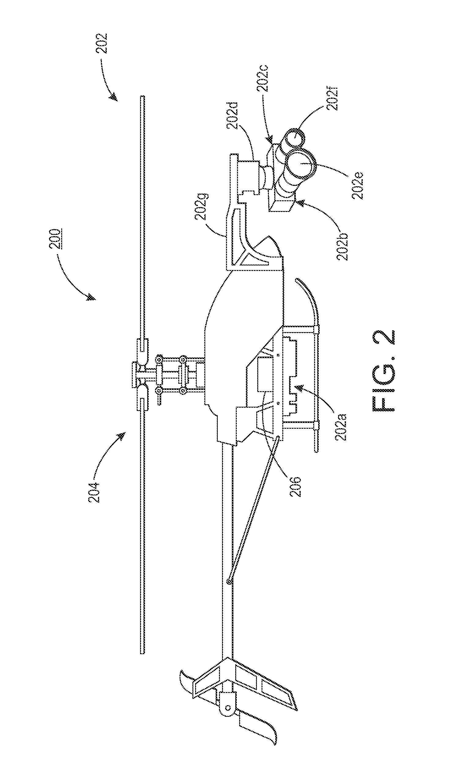
A method and system for measurement of ground based vehicle speed includes a movable platform that includes an unmanned aerial vehicle (UAV) located in proximity to a roadway, the UAV operates under control and navigation of a UAV control unit, and the UAV also carries camera and monitoring equipment, the camera and monitoring equipment including an onboard computing system, and a camera with a wide angle lens and a camera with a telephoto lens, the cameras being mounted on a pan / tilt device. An algorithm operated by the on-board computing system is used to detect and track vehicles moving on a roadway. The algorithm is configured to detect and track the vehicles despite motion created by movement of the UAV. The cameras mounted on the pan / tilt device are moved under the direction of the computer vision algorithm to maintain a target vehicle of the detected moving vehicles in view, and the speed of the target vehicle is measured.

Description

INCORPORATION BY REFERENCE[0001]The following co-pending and commonly assigned application, the disclosure of which is being totally incorporated herein by reference, is mentioned: U.S. patent application No. [Atty. Docket No. 20130009-US-NP], filed [unknown], entitled “System and Method for Visual Motion Based Object Segmentation and Tracking”, by Saund et al.BACKGROUND[0002]This application pertains to camera based analysis of road traffic. An existing issue is to detect a moving vehicle, measure its speed, and track the vehicle to capture an image of the vehicle's license plate. This is desired to be done from a mobile camera platform which is nominally an Unmanned Aerial Vehicle, however it is to be appreciated that other camera platforms are considered as well.[0003]Multiple ground-based technologies are available for detecting traffic law violations such as speeding, unsafe lane changes, running red lights, illegal turns, etc. Human operated speed detection is commonly accompl...

Claims


Application Information

Patent Timeline
Patent Type & Authority Applications(United States)
IPC IPC(8): G08G1/054G06V20/13G06V20/17
CPCG08G1/054G05D1/0094G08G5/00G06T2207/10032G06T2207/30236G06T7/215G06T7/246G06V20/13G06V20/54G06V10/255G06V2201/08G06V20/17B64U2101/30G08G1/0175
Inventor SAUND, ERICPAULSON, CHRISTOPHERBURTON, GREGORYPEETERS, ERIC
Owner CONDUENT BUSINESS SERVICES LLC
Learn More