System and method for determining and correcting field sensors errors

a field sensor and error correction technology, applied in the field of system and method for determining errors or biases, can solve problems such as large movements, sensor biases that may change over time, and all these sensors can be affected by biases

Active Publication Date: 2014-11-13
THE JOHN HOPKINS UNIV SCHOOL OF MEDICINE
View PDF20 Cites 28 Cited by
  • Summary
  • Abstract
  • Description
  • Claims
  • Application Information

AI Technical Summary

Benefits of technology

[0011]The present invention overcomes the aforementioned drawbacks by providing systems and methods that can continuously determine and correct or compensate for sensor error of field sensors, such as magnetometers and accelerometers. In particular, the present invention can use angular rate data obtained, for example, from a gyroscope and relate it to the sensor measurement rates to continually or periodically estimate and correct sensor error.

Problems solved by technology

However, all these sensors can be affected by biases, scale factors, and non-orthogonality of their measurements.
Unfortunately, these methods require large movements to measure a large angular range of outputs from the sensor.
Furthermore, sensor bias may change over time.
Such methods for determining sensor bias are precluded from addressing sensor bias that may vary over time or with changes in operating conditions.
Furthermore, changes in sensor bias over time or in response to changes in operating conditions can only be addressed by such calibration methods by recalibrating the device upon recognizing a change in sensor bias.
Unfortunately, such calibration methods do not easily provide a way to identify changes in sensor bias without performing a full recalibration of sensor bias.
Accordingly, such methods are ill suited to address changes in sensor bias over time or in response to changes in operating conditions.
This approach, however, requires numerical integration of the gyroscope data, which can be computationally intensive, particularly for systems without excess processing power.
Furthermore, such approaches cannot continuously calculate sensor bias.
This approach is often limited to compass bias calibration and, because the approach relies on numerical integration, it is inherently limited in the calibration process.

Method used


Image

  • System and method for determining and correcting field sensors errors
  • System and method for determining and correcting field sensors errors
  • System and method for determining and correcting field sensors errors

Examples


Embodiment Construction

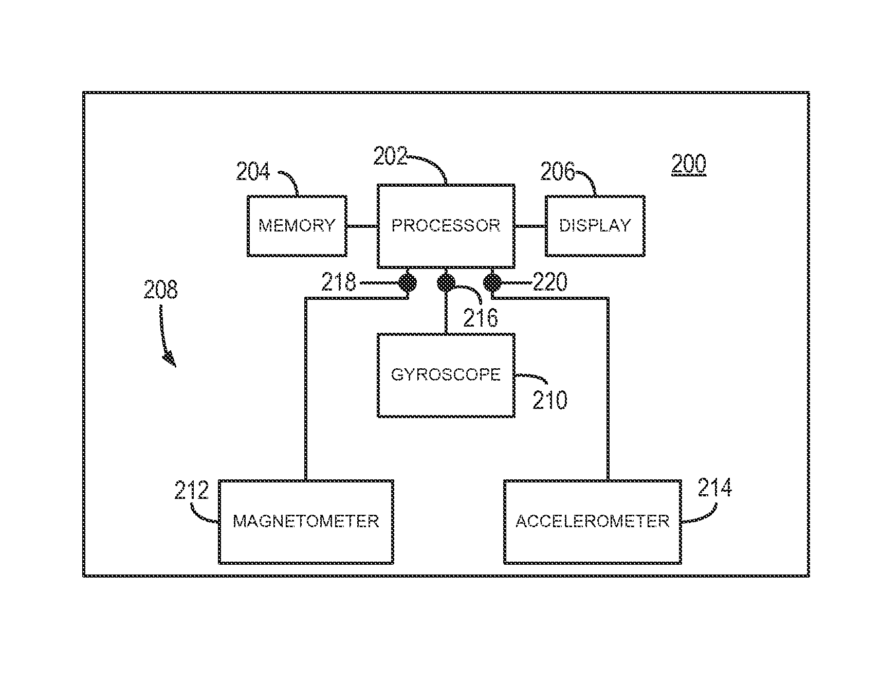
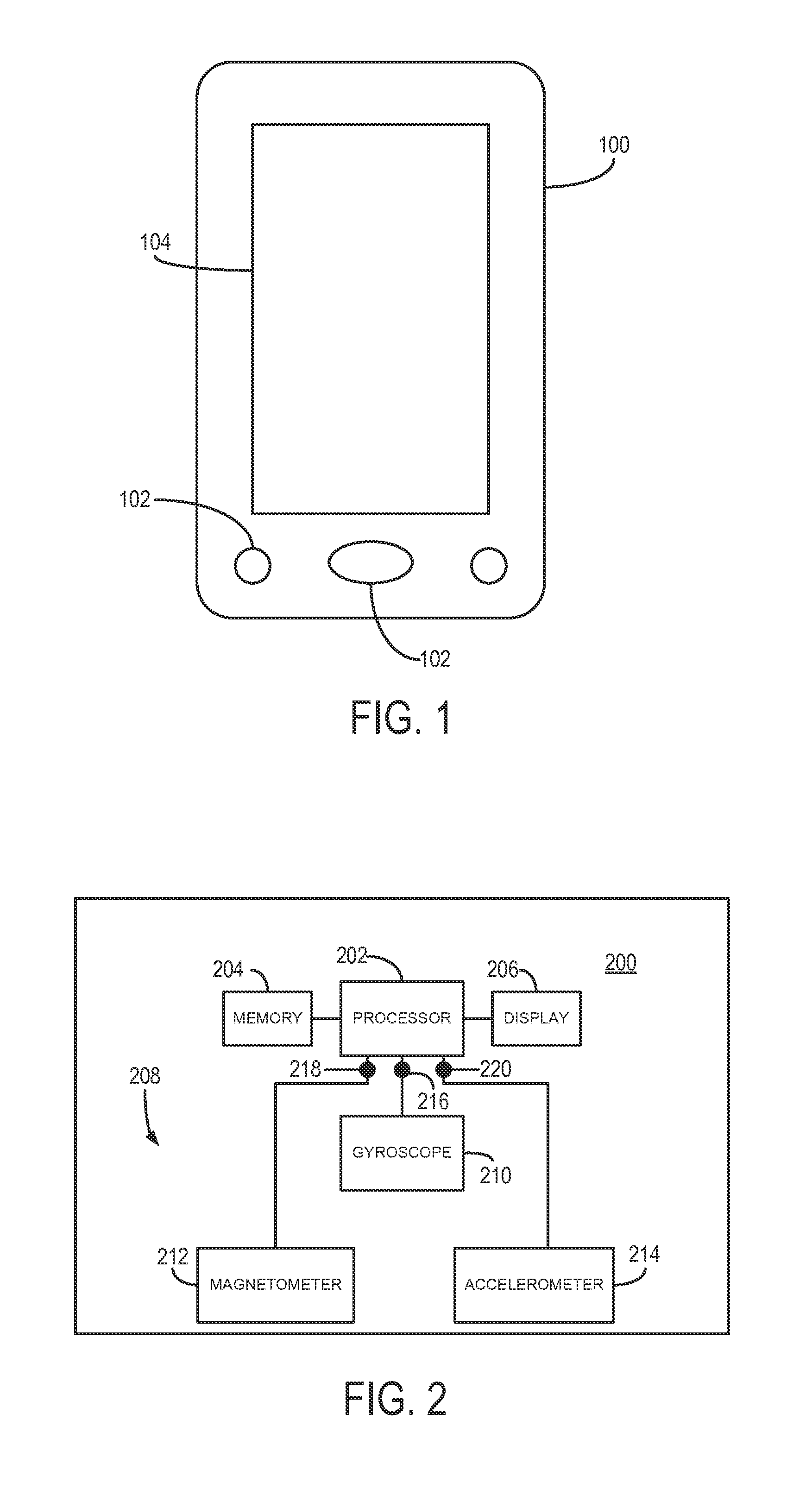
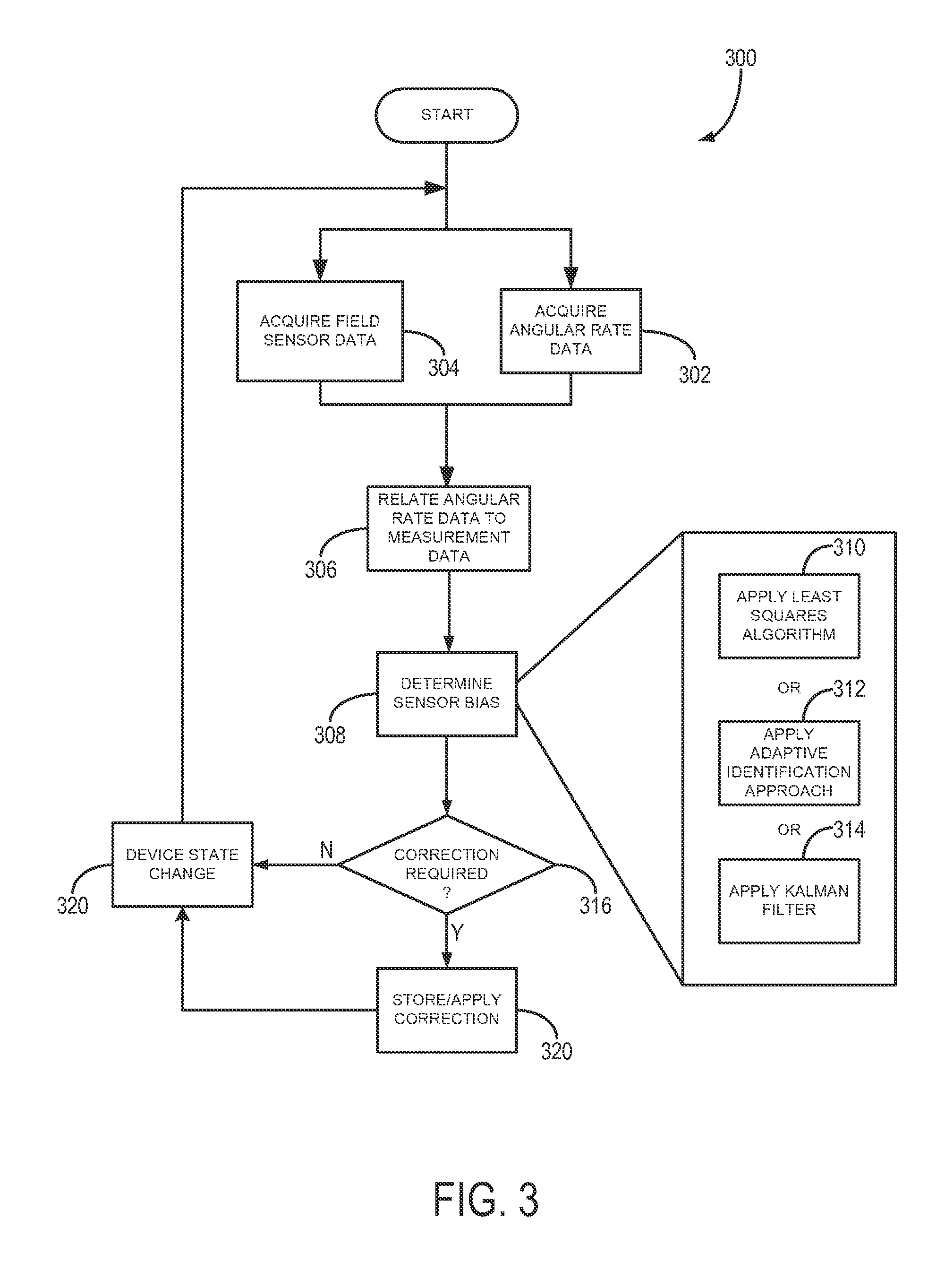
[0019]As discussed, three-axis magnetometers, three-axis accelerometers, and other field sensors are widely used sensors for attitude estimation, yet suffer from limited accuracy because of sensor measurement errors. As will be described, a system and method for estimating the sensor errors of a multi-axis field sensors, such as magnetometers and accelerometers. Multi-axis angular velocity measurements, such as may be provided by an angular-rate gyroscope, can be used to estimate the multi-axis field sensor measurement error and, based thereon, correct for such errors. These systems and methods do not require knowledge of the direction of the field (e.g. the local magnetic field or the local gravitational field) or the attitude of the device associated with the sensor, but can ensure convergence for the estimated parameters.

[0020]Referring particularly now to FIG. 1, an exemplary device 100 is shown. The device 100 may be, for example, a mobile device, such as vehicle navigation sys...


PUM


Abstract

A system and method for determining errors and calibrating to correct errors associated with field sensors, including bias, scale, and orthogonality, includes receiving and providing to a processor angular rate data and a first field vector relative to a first reference directional field and a second field vector relative to a second reference field from at least one field sensor. The processor is configured to relate the first field vector and the second field vector to the angular rate data to determine an error of the at least one field sensor. The processor is also configured to identify a compensation for the error of the at lease one field sensor needed to correct the first field vector and the second field vector and repeat the preceding to identify changes in the error over time and compensate for the changes in the error over time.

Description

STATEMENT REGARDING FEDERALLY SPONSORED RESEARCH[0001]This invention was made with government support under 0812138 awarded by the National Science Foundation. The government has certain rights in the invention.CROSS-REFERENCE TO RELATED APPLICATIONS[0002]N / ABACKGROUND OF THE INVENTION[0003]The present invention relates to systems and methods for correcting errors, such as bias, and error changes in field sensors. More particularly, the invention relates to systems and methods for determining errors or bias and changes in errors or bias of field sensors, such as magnetometers and accelerometers, using angular rate data.[0004]Magnetometers (or compasses), accelerometers, and gyroscopes are widely used in many applications including vehicle navigation systems and in electronics devices such as so-called smart-phones, mobile computing devices including tablets, and an ever-increasing range of systems. Magnetometers are used to measure Earth's local magnetic field vector with respect to...

Claims


Application Information

Patent Timeline
Patent Type & Authority Applications(United States)
IPC IPC(8): G01C25/00
CPCG01C25/00G01C25/005G01C17/38
Inventor TRONI-PERALTA, GIANCARLOWHITCOMB, LOUIS L.
Owner THE JOHN HOPKINS UNIV SCHOOL OF MEDICINE
Why Eureka
Try Eureka