Sensor element, electronic apparatus and moving object

a technology of electronic equipment and moving objects, applied in the direction of flexible microstructure devices, speed/acceleration/shock measurement, instruments, etc., can solve the problems of movable body coming into contact with the protruding section, movable electrode pulling toward the fixed electrode, etc., to achieve the effect of enhancing reliability

Active Publication Date: 2014-11-20
SEIKO EPSON CORP
View PDF5 Cites 35 Cited by
  • Summary
  • Abstract
  • Description
  • Claims
  • Application Information

AI Technical Summary

Benefits of technology

[0045]According to the moving object having this configuration, as the sensor element capable of suppressing contact of the movable body and the detection electrode section and continuously detecting acceleration or the like even if excessive acceleration or the like is applied is mounted, it is possible to enhance reliability.

Problems solved by technology

However, if the insulating layer on which the fixed electrode is provided is charged, there is a concern that the movable electrode is pulled toward the fixed electrode due to an electrostatic attraction (pulling force) generated by the charging.
If the movable body is excessively displaced, the movable body comes into contact with the protruding section.

Method used


Image

  • Sensor element, electronic apparatus and moving object
  • Sensor element, electronic apparatus and moving object
  • Sensor element, electronic apparatus and moving object

Examples


first embodiment

[0059]A sensor element according to a first embodiment will be described with reference to FIG. 1 to FIGS. 3A, 3B and 3C.

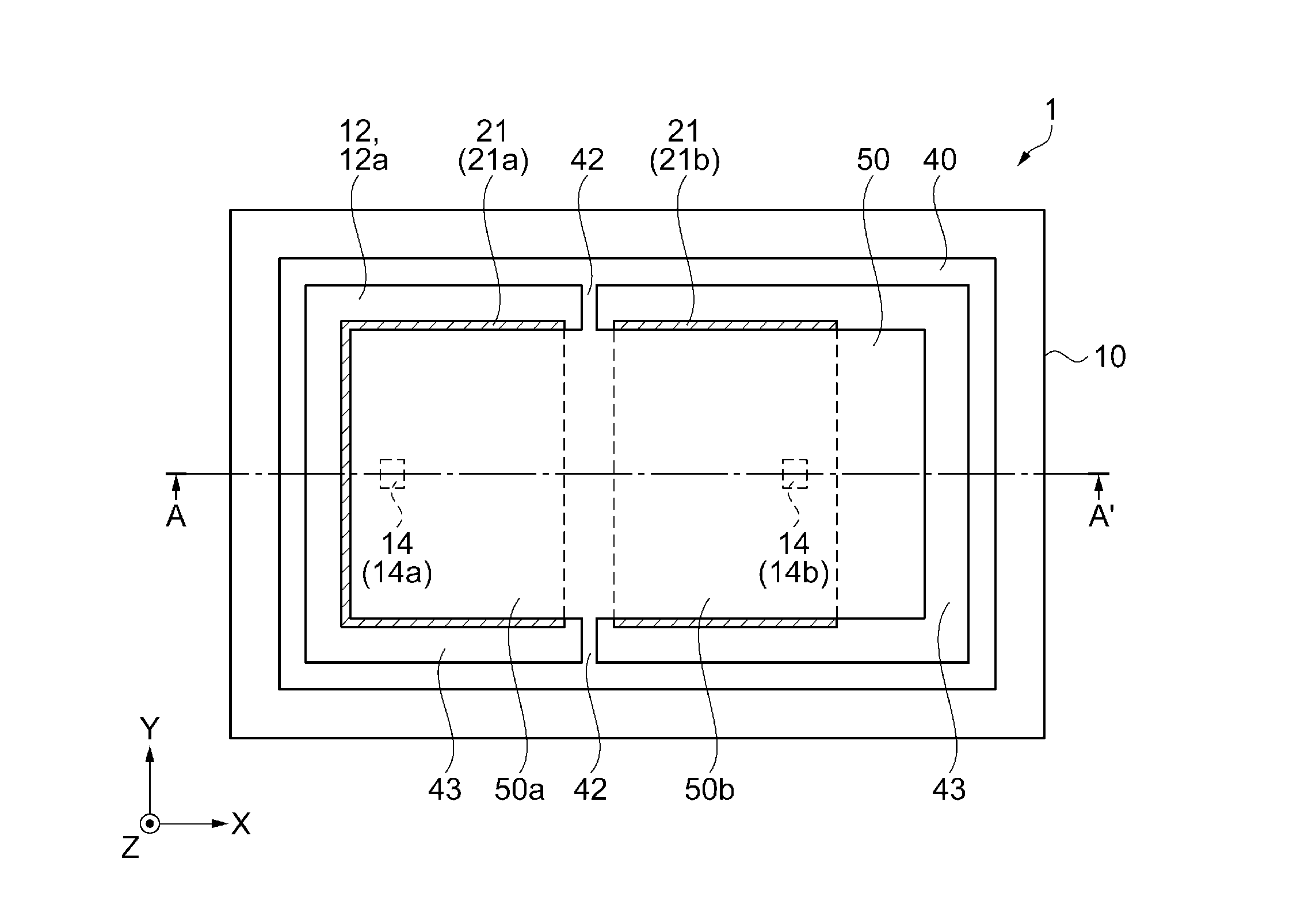
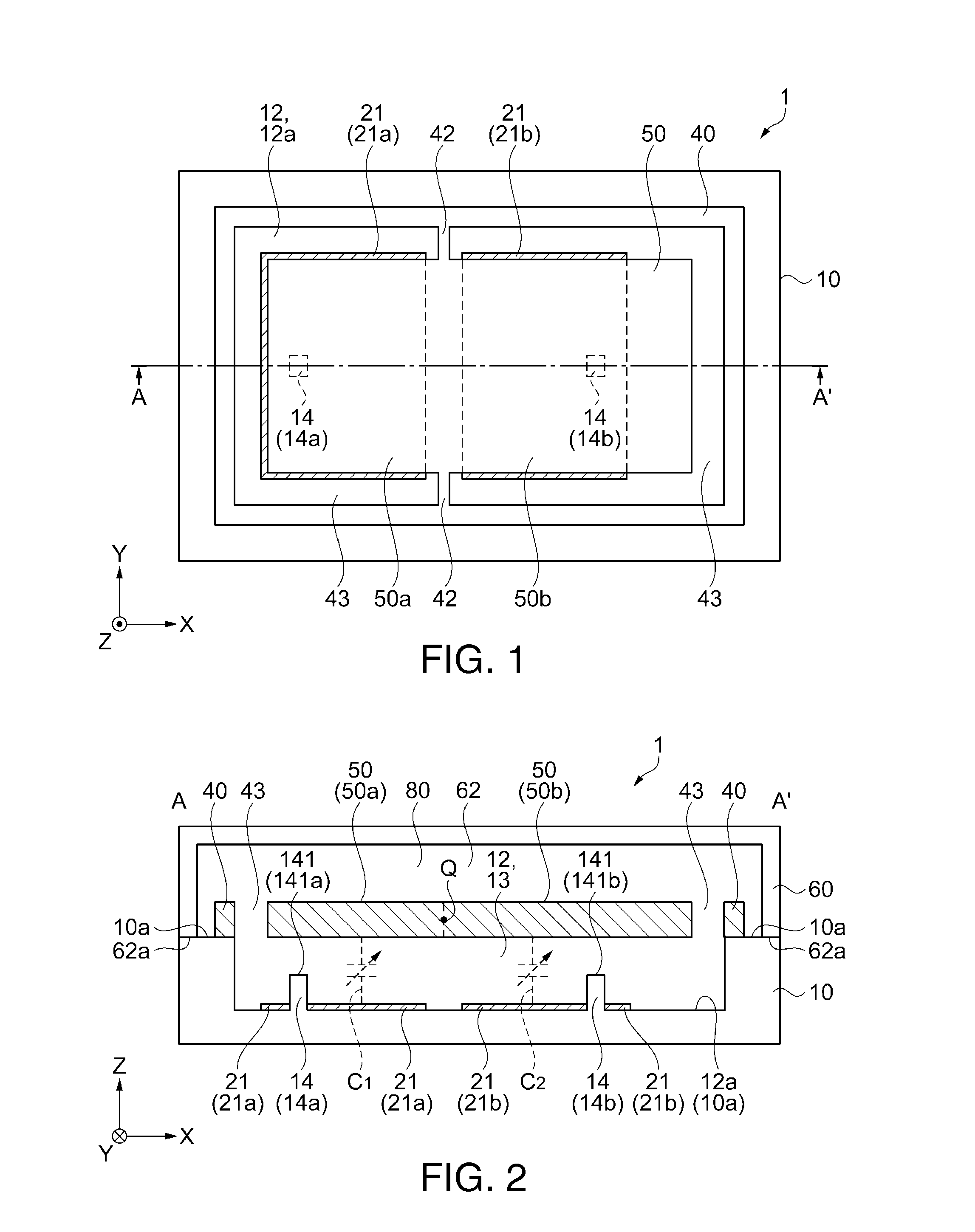
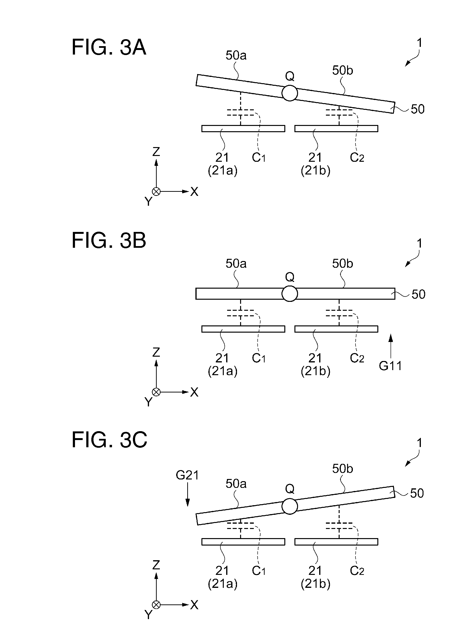
[0060]FIG. 1 is a plan view schematically illustrating a sensor element according to the first embodiment. FIG. 2 is a cross-sectional view schematically illustrating the sensor element taken along line A-A′ in FIG. 1. FIGS. 3A to 3C are diagrams schematically illustrating an operation of the sensor element according to the first embodiment.

[0061]For ease of description, a cover is not shown in FIG. 1. Further, only a movable body and a detection electrode section are shown in FIGS. 3A to 3C. In FIG. 1 to FIGS. 3A, 3B and 3C, an X axis, a Y axis and a Z axis are shown as three axes that are orthogonal to each other. The Z axis is an axis indicating a thickness direction where the cover overlaps a substrate.

[0062]Structure of sensor element 1

[0063]The sensor element 1 of the present embodiment may be used as an inertial sensor, for example. Specifically, the sensor...

second embodiment

[0130]A sensor element according to a second embodiment will be described with reference to FIG. 4.

[0131]FIG. 4 is a cross-sectional view schematically illustrating the sensor element according to the second embodiment. FIG. 4 is a diagram schematically illustrating a cross section of the sensor element, taken along line A-A′ in FIG. 1.

[0132]In FIG. 4, the X axis, the Y axis and the Z axis are shown as three axes that are orthogonal to each other. The Z axis is an axis indicating a thickness direction where a cover overlaps a substrate.

[0133]A sensor element 1a according to the second embodiment is different from the sensor element 1 described in the first embodiment in that a dummy electrode section 22 is provided on the first bottom surface 12a of the first recessed section 12 provided in the substrate 10. Since the other configurations and the like in the sensor element 1a are approximately the same as in the sensor element 1, the same reference numerals are given to the same com...

third embodiment

[0145]A sensor element according to a third embodiment will be described with reference to FIG. 5.

[0146]FIG. 5 is a cross-sectional view schematically illustrating the sensor element according to the third embodiment. FIG. 5 is a diagram schematically illustrating a cross section of the sensor element, taken along line A-A′ in FIG. 1.

[0147]In FIG. 5, the X axis, the Y axis and the Z axis are shown as three axes that are orthogonal to each other. The Z axis is an axis indicating a thickness direction where a cover overlaps a substrate.

[0148]A sensor element 1b according to the third embodiment is different from the sensor element 1a described in the second embodiment in that groove sections 16 are provided in the first bottom surface 12a of the first recessed section 12 provided in the substrate 10. Since the other configurations in the sensor element 1b and the like are approximately the same as in the sensor elements 1 and 1a, the same reference numerals are given to the same compo...


PUM


Abstract

A sensor element includes: a detection electrode section; a movable body that is provided to face the detection electrode section; and a protruding section that is provided in a region where the detection electrode section is provided in a plan view of the detection electrode section seen in a vertical direction and protrudes toward the movable body. At least a part of a surface of the protruding section is made of an insulating material.

Description

BACKGROUND[0001]1. Technical Field[0002]The present invention relates to a sensor element, an electronic apparatus, and a moving object.[0003]2. Related Art[0004]In the related art, as a sensor element that detects a physical quantity such as acceleration, a sensor element including a movable body that is a movable electrode supported by a support section to be capable of oscillating and a detection electrode section that is a fixed electrode section disposed at a position that faces the movable body has been proposed. In such a sensor element, as the movable body oscillates according to a force applied to the sensor element, a distance between the movable body and the detection electrode section is changed. The detection of acceleration or the like applied to the sensor element is performed based on change in an electrostatic capacitance generated between both the electrode sections due to the distance change. For example, Japanese Patent No. 4605087 discloses an electrostatic capa...

Claims


Application Information

Patent Timeline
Patent Type & Authority Applications(United States)
IPC IPC(8): G01P15/125
CPCG01P15/125B81B3/0008B81B2201/0235G01P2015/0831G01P2015/0871
Inventor TAKAGI, SHIGEKAZU
Owner SEIKO EPSON CORP
Why Eureka
Try Eureka