Arc extinguishing chamber for an electric protection apparatus and electric protection apparatus comprising same

a technology for electric protection apparatuses and extinguishing chambers, which is applied in the direction of electrical apparatuses, air-break switches, high-tension/heavy-dress switches, etc., can solve the problems of increasing the cost, disturbing the removal of breaking gases, and degrading the quality of breaking more or less greatly, so as to improve the energy capacity of the apparatus and improve the quality of breaking

Active Publication Date: 2014-11-20
SCHNEIDER ELECTRIC IND SAS
View PDF6 Cites 2 Cited by
  • Summary
  • Abstract
  • Description
  • Claims
  • Application Information

AI Technical Summary

Benefits of technology

[0009]The present invention solves these problems and proposes an arc extinguishing chamber for an electric protection apparatus, and an electric protection apparatus comprising same, enabling the quality of breaking to be improved so as to improve the energy capacity of the apparatus.
[0010]For this purpose, the object of the present invention is to provide an arc extinguishing chamber of the above-mentioned kind, this extinguishing chamber being characterized in that it comprises a wall called balancing wall, substantially solid at least on its central part, said wall being located downstream from the arc extinguishing chamber and being formed and arranged with respect to the arc extinguishing chamber in such a way as to slow down the exhaust flow of the breaking gases on the side of the arc extinguishing chamber where the gases go first and enhancing flow of the exhaust gases on the opposite side, the exhaust gases being stopped by the central part of the wall and escaping via the edges of the wall.
[0013]This feature presents the additional advantage of eliminating the use of an insulating grid usually used to prevent the arc from establishing itself downside from the chamber, and usually located by necessity very close to the chamber.
[0015]This balancing partition does in fact perform the same functions as the grid, apart from its first function which is to balance flow of the gases, does not need to be placed as close to the extinguishing chamber as the grid, presents very limited melting and vaporisation, which enables it not to disturb the flow of the gases, but suffices to keep the arc in the chamber. In addition, this partition also presents the advantage of being more robust than a grid and of being easier to mould.
[0022]Thus, according to this embodiment, a single part performs three functions, i.e. securing of the fins, balancing of the gas flow, and limiting of the re-breakdown risks.

Problems solved by technology

In known circuit breakers, in particular miniature current limiting circuit breakers, it has been observed that after switching of the arc and displacement of the latter to the breaking chamber in the direction of the extinguishing chamber, re-breakdown phenomena occur which more or less greatly degrade the quality of breaking.
This insulating grid placed downstream from the extinguishing chamber is formed either by an additional non-meltable part (thermosetting fibre or plastic), which increases the cost, either by addition of a suitable shape moulded with the thermoplastic case, which melts when the apparatus is subjected to several successive short-circuits, which further disturbs removal of the breaking gases.
It is known that these re-breakdown phenomena are due to a poor insertion of the arc in the extinguishing chamber, this defective insertion being due to a badly controlled flow of the gases.
Depending on the arrangement of the removal channels downstream from the chamber, this first circulation can hamper or even prevent circulation of the hot gases between the other fins, thereby preventing balanced insertion of the arc over the total height of the chamber.

Method used


Image

  • Arc extinguishing chamber for an electric protection apparatus and electric protection apparatus comprising same
  • Arc extinguishing chamber for an electric protection apparatus and electric protection apparatus comprising same
  • Arc extinguishing chamber for an electric protection apparatus and electric protection apparatus comprising same

Examples


Embodiment Construction

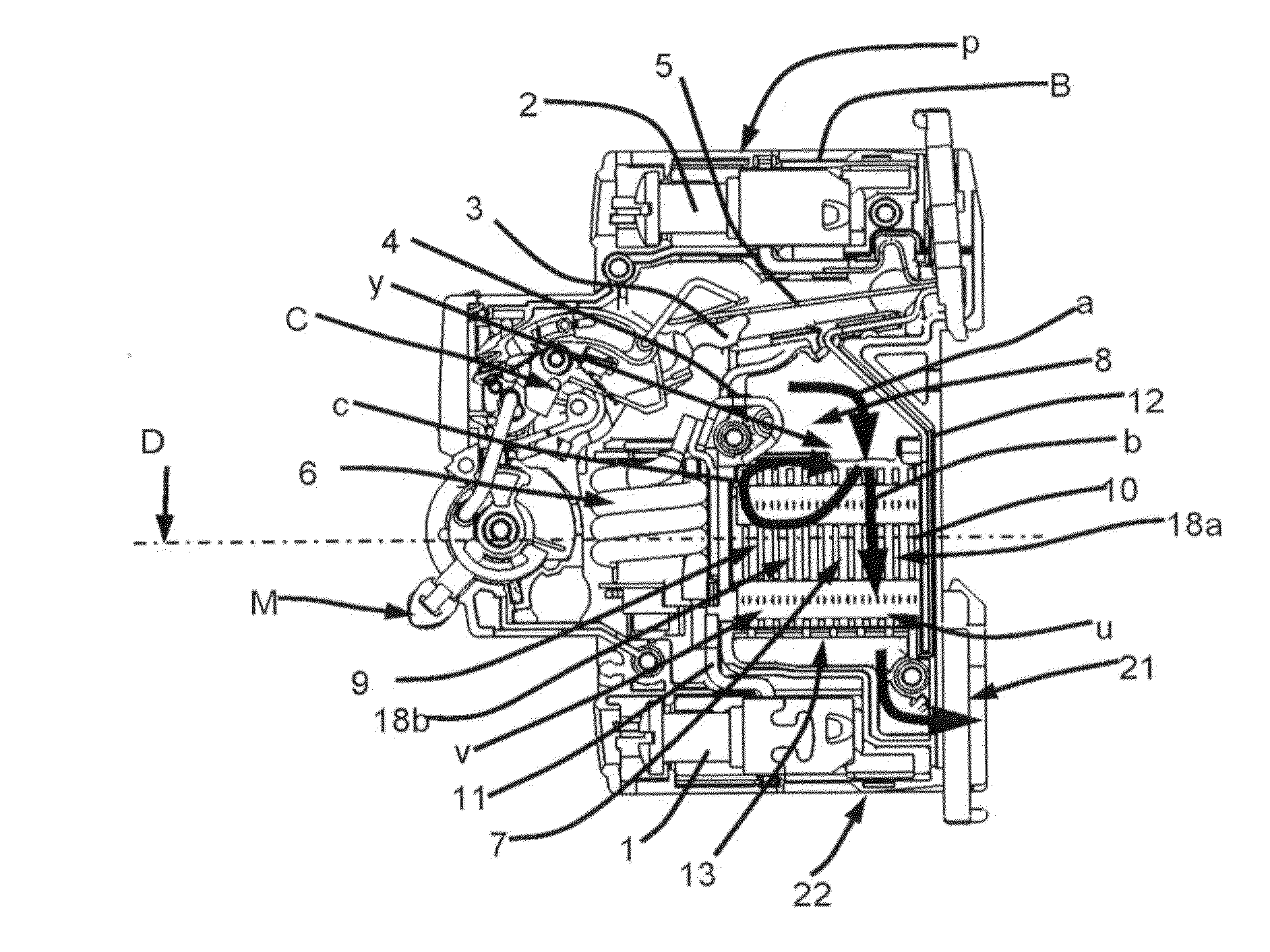
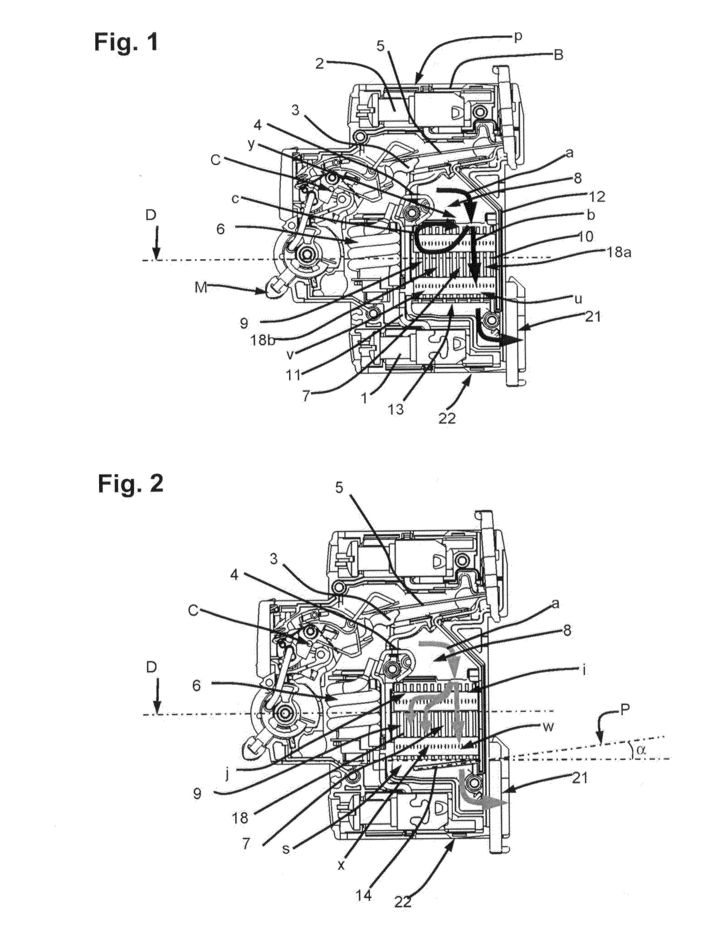
[0034]In FIGS. 1, 2, 4, 6, 9, 10, a pole p of a miniature circuit breaker can be seen comprising an insulating case B having an operating handle M on its front panel and connection terminals 1,2 on its two narrow side panels. A movable contact 3 and a stationary contact 4 are housed inside the case, in a manner known as such.

[0035]The movable contact 3 is controlled by an operating mechanism C connecting the above-mentioned handle M to the movable contact for closing or opening of the contacts.

[0036]A thermal trip release 5 and an electromagnetic trip release 6, designed to perform automatic opening of the contacts 3,4 in case of an overload or a short-circuit, are also housed in this case.

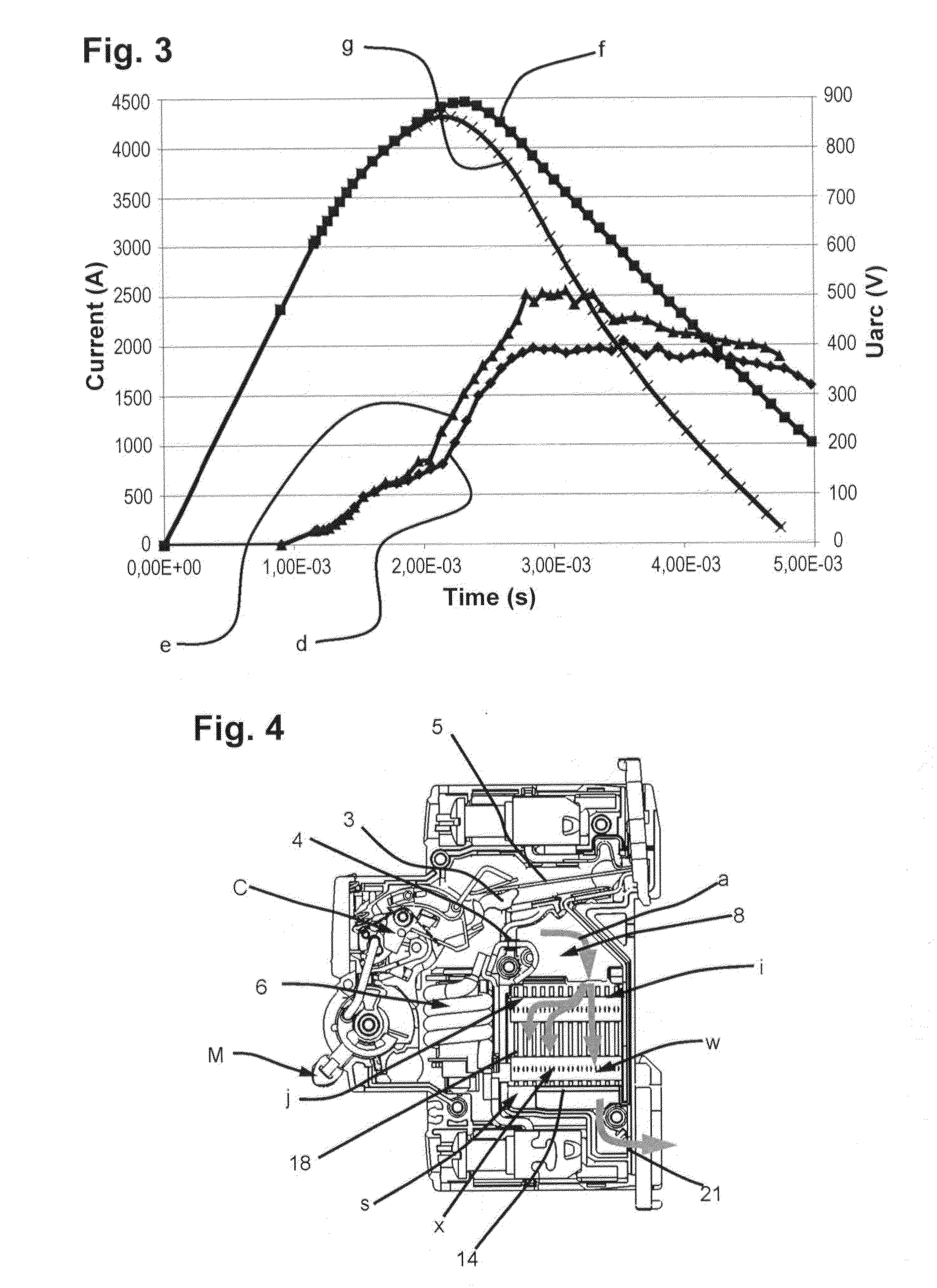
[0037]The bottom part of the case B contains a breaking chamber 7 formed by a first chamber called arc formation chamber 8 communicating with the inlet of a second chamber called arc extinguishing chamber, the latter comprising fins 10.

[0038]The movable contact 3 extends substantially perpendicula...


PUM


Abstract

The present invention relates to an arc extinguishing chamber of an electric protection apparatus comprising an arc formation chamber containing a stationary contact and a movable contact which, when they separate, form an arc between them, said arc formation chamber communicating with the inlet of a second chamber, called arc extinguishing chamber. This chamber comprises a wall called balancing wall, substantially solid at least on its central part, said wall being located downstream from the arc extinguishing chamber and being formed and arranged with respect to the arc extinguishing chamber in such a way as to slow down the exhaust flow of the breaking gases on the side of the arc extinguishing chamber where the gases go first, and enhancing flow of the exhaust gases on the opposite side, the exhaust gases being stopped by the central part of the wall and escaping via the edges of the wall.

Description

BACKGROUND OF THE INVENTION[0001]The present invention relates to an arc extinguishing chamber for an electric protection apparatus comprising an arc formation chamber containing a stationary contact and a movable contact which, when they separate, form an arc between them, said arc formation chamber communicating with the inlet of a second chamber, called arc extinguishing chamber.STATE OF THE PRIOR ART[0002]In known circuit breakers, in particular miniature current limiting circuit breakers, it has been observed that after switching of the arc and displacement of the latter to the breaking chamber in the direction of the extinguishing chamber, re-breakdown phenomena occur which more or less greatly degrade the quality of breaking.[0003]Certain of these apparatuses, such as those described for example in the documents EP 1 017 072 or FR 2 471 661, comprise elements forming insulating grids located downstream from the arc extinguishing chamber, the openings of which are designed to ...

Claims


Application Information

Patent Timeline
Patent Type & Authority Applications(United States)
IPC IPC(8): H01H33/08
CPCH01H33/08H01H9/342H01H9/345H01H33/00
Inventor MOREAU, LUCRONDOT, LOIC
Owner SCHNEIDER ELECTRIC IND SAS
Why Eureka
Try Eureka