Dual independent control hydraulic switch machine

a hydraulic switch and independent control technology, applied in the field of switch machines, can solve the problems of difficult constant monitoring of the machine, difficult to ensure the reliability of the power source, and easy failure, so as to avoid the possibility of injuring a nearby worker

Active Publication Date: 2014-11-20
VOESTALPINE RAILWAY SYST NORTRAK LLC
View PDF4 Cites 2 Cited by
  • Summary
  • Abstract
  • Description
  • Claims
  • Application Information

AI Technical Summary

Benefits of technology

[0013]In one aspect, the invention comprises a switch machine for switch stands controlling points at a switch. In power operation mode, the machine may be operated remotely, or using controls located on the machine. In the event of power or hydraulic failure, the machine may be operated manually. The machine comprises a dual disconnect mechanism to disconnect the hydraulic throw mechanism when the machine is operating in manual mode and prevent unexpected movement of the manual throw mechanism, which could injure a worker attempting to manually throw the switch points. Similarly, the dual disconnect mechanism disconnects the manual throw mechanism when the machine is operating in power mode, such that movement of the switch points will not move the manual throw mechanism, avoiding the possibility of injuring a nearby worker.

Problems solved by technology

While hydraulic machines generally contain fewer parts than electrical machines and therefore are simpler and cheaper to construct and maintain, electrical machines were said to be an improvement over hydraulic machines because the hydraulic machines could be susceptible to failure due to leakages in the machine itself as well as all external pipes, conduits and hoses, and because hydraulic machines require an external source of hydraulic power, which is not always readily available.
However, electrically powered machines also require a power source to operate the machine.
In some lightly populated or underdeveloped areas, it may be difficult to ensure that a reliable power source is always available, and also difficult to constantly have someone checking the machine.
Further, if for some reason a power source is unavailable, a powered switch machine is inoperable.
However, none of Wyatt, Bowles or Beaman addresses the issue of manually actuating the machine if hydraulic pressure is not available.
Another potential issue with such machines is the nature of the control over the operating mode.
If an operator is in the process of manually throwing a switch and power is suddenly restored to the machine, the interdependence between the power and manual operating modes generally means that the manual throw lever could suddenly begin to move on its own with great force, potentially causing serious injuries to the operator.
In electrical switch machines, this issue has been typically addressed by disrupting the power circuit when the switch machine operates in manual mode.
One drawback with this type of system is the possibility of tampering; with an electric motor, it is possible to bypass the cutout switch and allow the motor to operate even if the system appears to be in manual mode.
Again, this is not completely fail-safe, as a hydraulic motor could itself be shorted to provide power, even if its battery is disconnected.

Method used


Image

  • Dual independent control hydraulic switch machine
  • Dual independent control hydraulic switch machine
  • Dual independent control hydraulic switch machine

Examples


Embodiment Construction

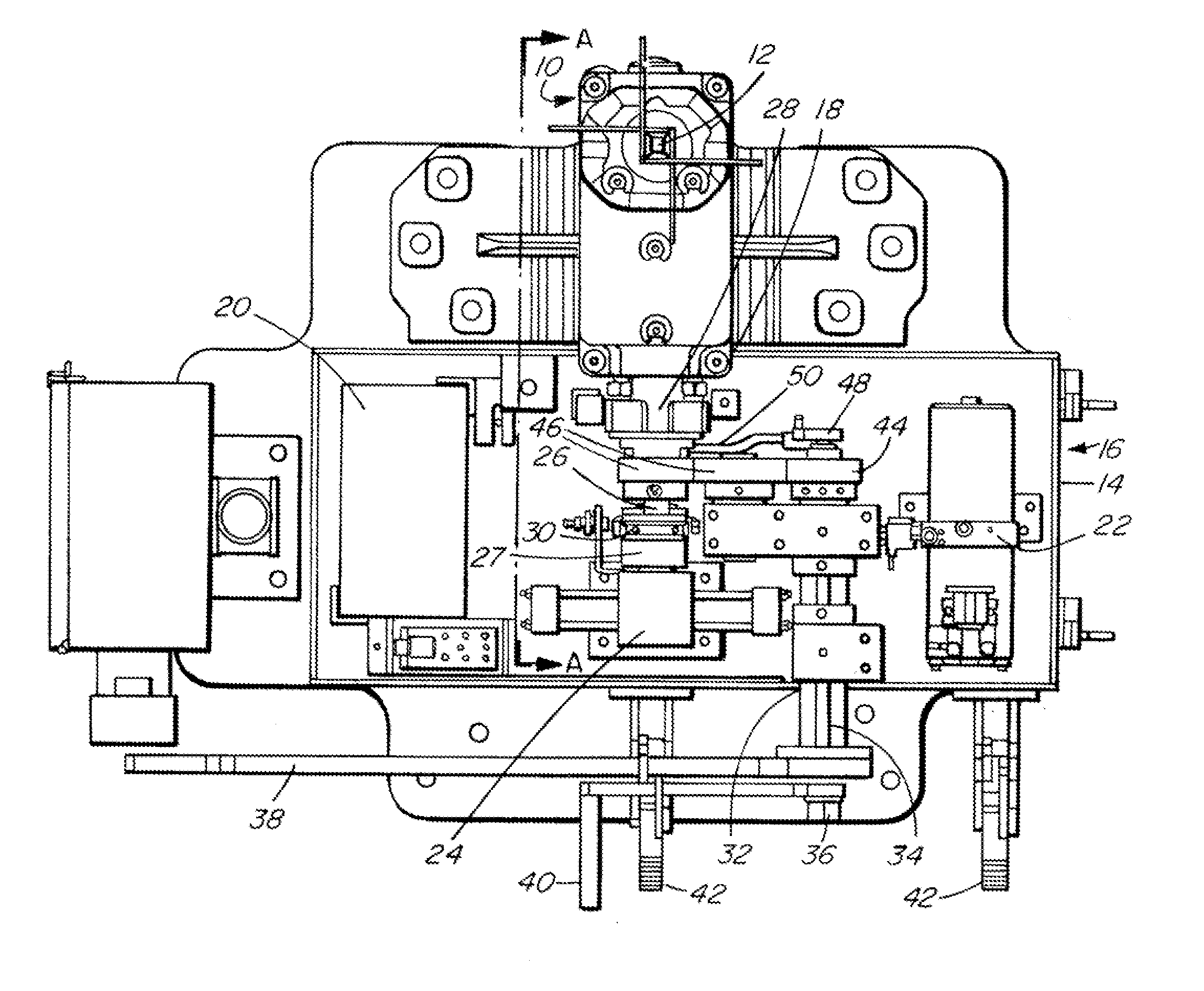
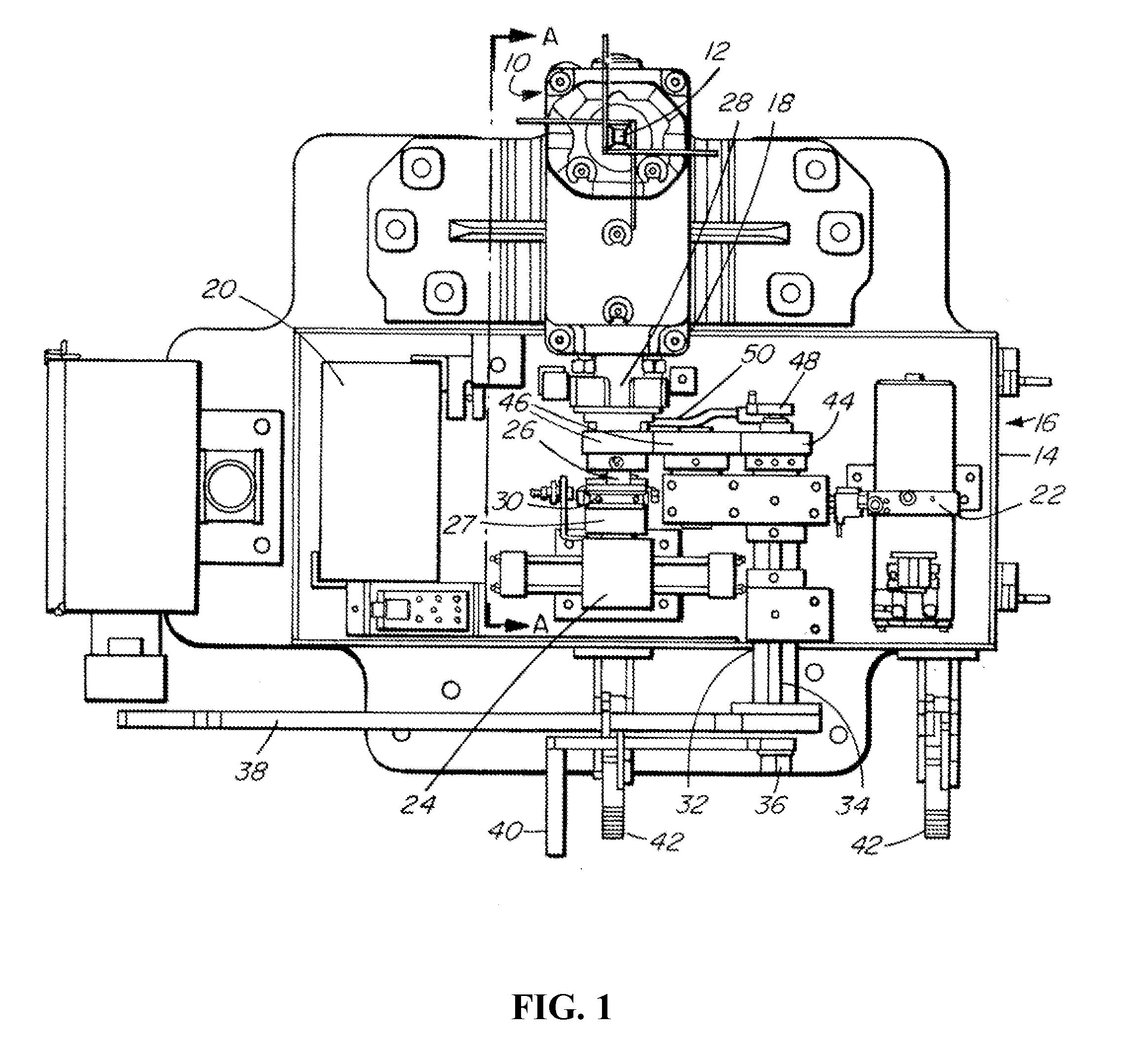
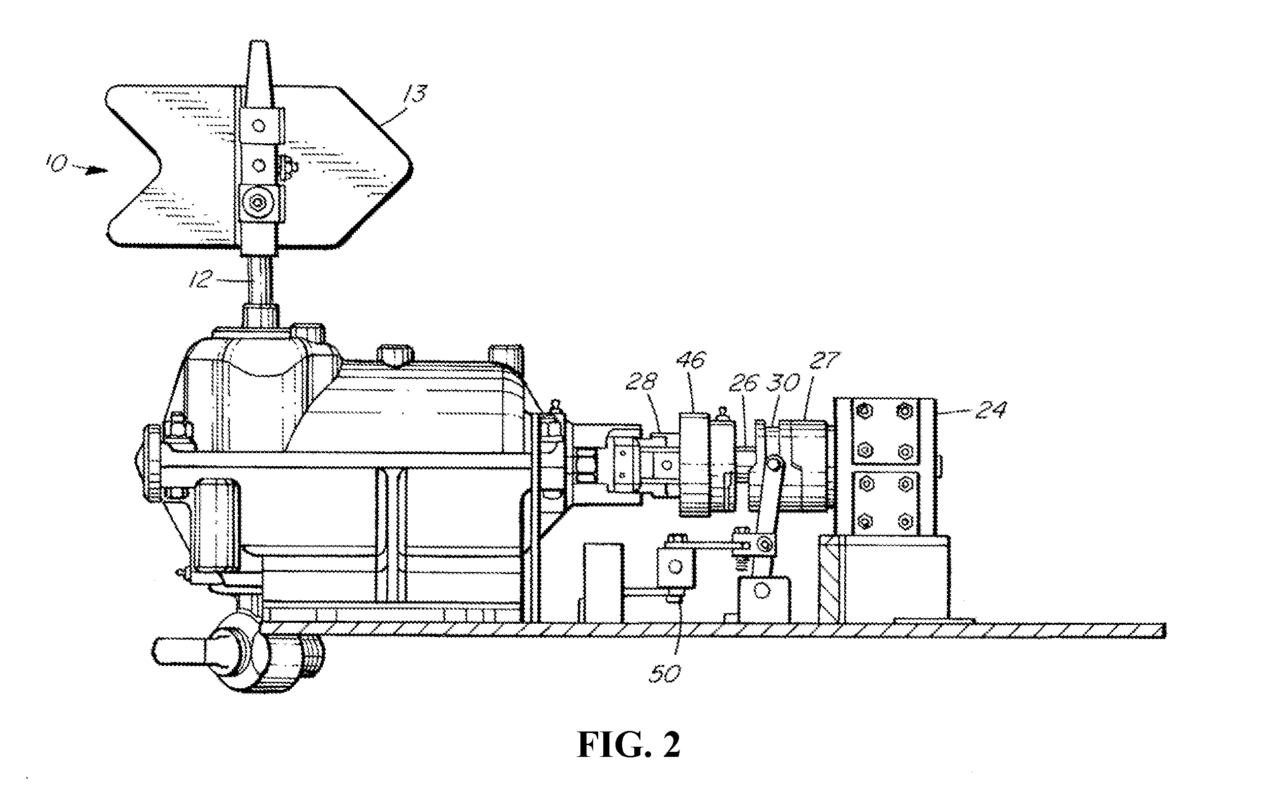
[0028]Referring to FIGS. 1 and 2, a switch stand 10 is adapted to be connected to the railroad switch points (not shown) to move the points between first and second positions. A pivoting shaft or spindle 12 is operatively connected to the switch points and carries a target 13 to indicate whether the switch points are in the first or second position. A housing 14 for the switch machine 16 has a cover (not shown) and a first opening 18 through which the switch machine 16 is connected to the switch stand 10 to translate movement within the switch machine 16 to movement of the switch points.

[0029]The housing 14 contains operating mechanisms for both manual and power operating modes, as well as a dual disconnect mechanism by which either the manual or power operating mechanism is rendered inoperable once the other operating mode is chosen.

[0030]The power operating mechanism is a hydraulic actuation system that includes a hydraulic power unit 22, which in turn actuates a hydraulic rotary ...


PUM


Abstract

A hydraulically powered switch machine having power and manual operating modes, and a dual disconnect mechanism. In power operation mode, the machine may be operated remotely, or using controls located on or near the machine. In the event of power failure, the machine may be operated manually. The dual disconnect mechanism physically disconnects the powered throw mechanism when the machine is operating in manual mode and physically disconnects the manual throw mechanism when the machine is operating in power mode, in both cases preventing unexpected movement of the manual throw mechanism.

Description

FIELD OF THE INVENTION[0001]This invention relates to switch machines. In particular, this invention relates to hydraulically operated switch machines having dual independent control mechanisms.BACKGROUND OF THE INVENTION[0002]Switch machines are used to move railroad switch points. Many machines are manually operated, requiring an operator to physically force a manual throwing device to move, working against the weight of the switch points and the effects of friction and inertia. In response to the high physical toll such machines took on the operator, switch machines, such as those described in U.S. Pat. No. 4,938,438 to Farrell, U.S. Pat. No. 5,419,518 to Fiorenzo and U.S. Pat. No. 5,494,243 to Kuhn, were improved to provide a better mechanical advantage and ease the physical load on the operator.[0003]Many switch machines also have power operating modes, such as those described in U.S. Pat. No. 5,775,647 to Wyatt, German Patent No. 3825182 to Windgassen et al., each of which dis...

Claims


Application Information

Patent Timeline
Patent Type & Authority Applications(United States)
IPC IPC(8): B61L5/04
CPCB61L5/04
Inventor CLICK, GARYDUFFNER, BRENT
Owner VOESTALPINE RAILWAY SYST NORTRAK LLC
Why Eureka
Try Eureka