
Balancing control circuit for battery cell module using lc series resonant circuit

a battery cell module and resonant circuit technology, applied in charge equalisation circuits, transportation and packaging, arrangements for several simultaneous batteries, etc., can solve the problems of battery receiving permanent damage, voltage imbalance, and the charge capacity of the battery cell module does not approach the rated charge capacity, so as to minimize the loss

Active Publication Date: 2014-11-20
POSTECH ACAD IND FOUND
View PDF3 Cites 32 Cited by
  • Summary
  • Abstract
  • Description
  • Claims
  • Application Information

AI Technical Summary

Benefits of technology

The present invention provides a balancing control circuit for a battery cell module that uses switching elements and an LC series resonant circuit to minimize hard switching loss. This results in a more efficient and effective balancing operation for the battery cell module.

Problems solved by technology

In general, when a voltage applied across a battery (battery cell) exceeds a predetermined value, the battery may explode, and when the voltage drops below a predetermined value, the battery may receive permanent damage.
However, when the battery cell module is used, a voltage imbalance may occur due to a difference in performance between the respective battery cells.
As a result, the charge capacity of the battery cell module does not approach the rated charge capacity.
However, when such a battery cell balancing circuit is used, power is consumed through the resistors.
Furthermore, since the upper-limit voltage cannot be supplied to a battery cell having a lower voltage while the battery module is used, the efficiency is reduced.
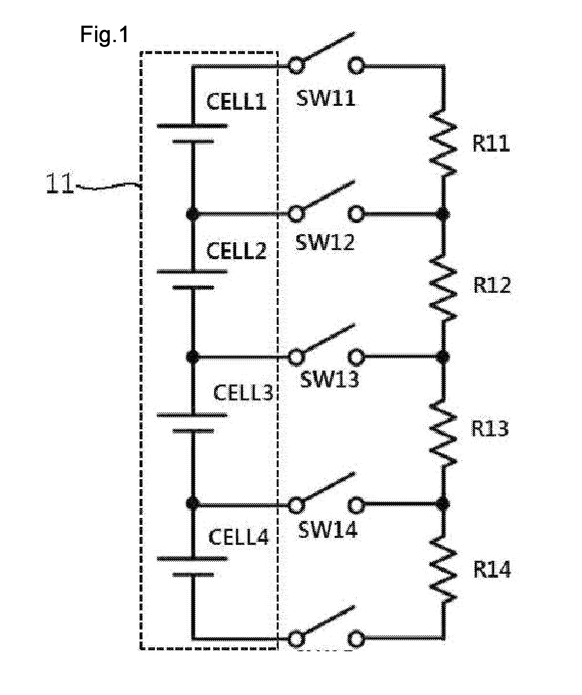
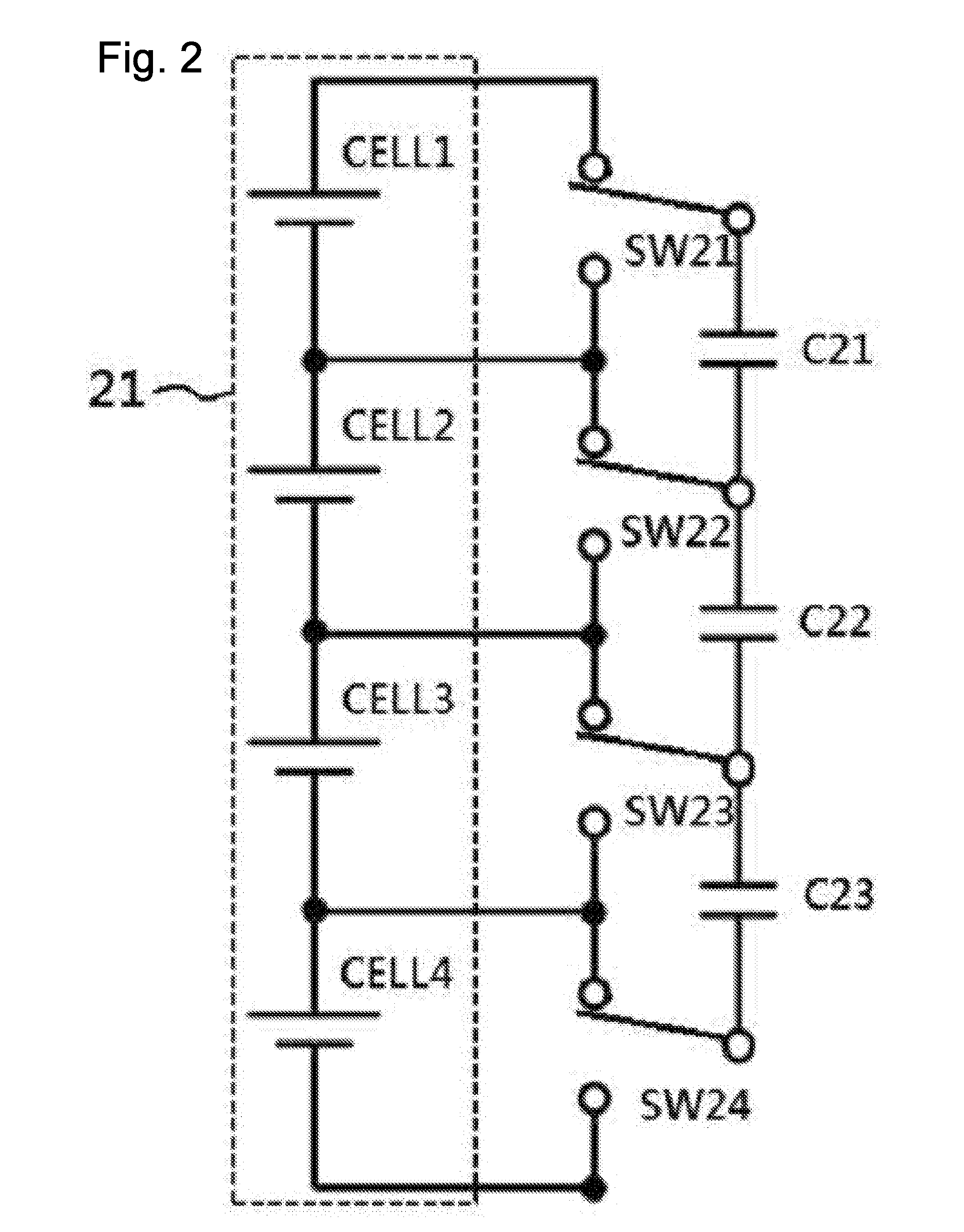
However, such a battery cell balancing circuit has a problem in that the efficiency thereof decreases because a hard switching operation occurs between a capacitor and a battery cell.
However, the conventional battery cell balancing circuit cannot perform the voltage transmission function.
However, with the increase in number of battery cells provided in the battery cell module, the size of a magnetic core used in the flyback converter is inevitably increased.
Thus, the price of the battery cell balancing circuit increases.
Furthermore, since the conventional battery cell balancing circuit does not have a function of properly controlling balancing speed, there are difficulties in improving the balancing efficiency or securing the cell stability.

Method used


Image

  • Balancing control circuit for battery cell module using lc series resonant circuit
  • Balancing control circuit for battery cell module using lc series resonant circuit
  • Balancing control circuit for battery cell module using lc series resonant circuit

Examples


Embodiment Construction

[0039]Reference will now be made in greater detail to a preferred embodiment of the invention, an example of which is illustrated in the accompanying drawings. Wherever possible, the same reference numerals will be used throughout the drawings and the description to refer to the same or like parts.

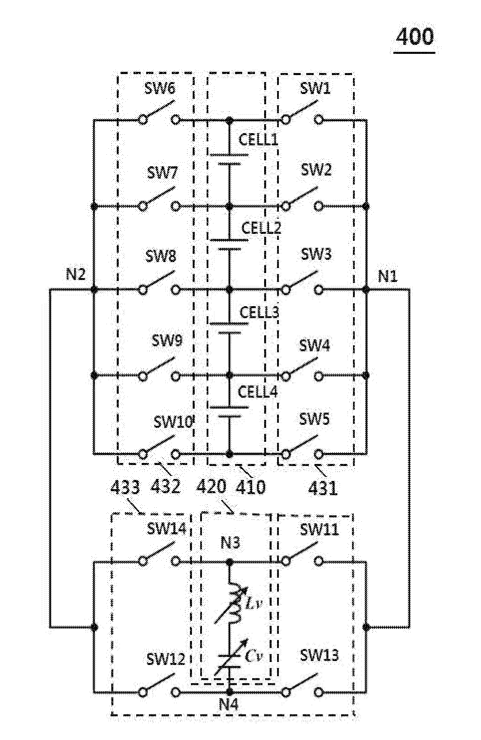
[0040]FIG. 4 is a diagram illustrating a balancing control circuit for a battery cell module using an LC series resonant circuit according to an embodiment of the present invention. Referring to FIG. 4, the balancing control circuit includes a battery cell module 410, a series resonant circuit 420, and a switch unit having first to third switch units 431 to 433.

[0041]The battery cell module 410 includes first to fourth battery cells CELL1 to CELL4 connected in series.

[0042]The series resonant circuit 420 includes an inductor unit Lv and a capacitor unit Cv which are connected in series. The inductor unit Lv may have a variable capacity, and the capacitor unit Cv may have a variable capacit...


PUM


Abstract

Provided is a battery cell balancing circuit including: a battery cell module including a plurality of battery cells connected in series; a series resonant circuit including an inductor unit and a capacitor unit which are connected in series so as to store electric energy recovered from a corresponding battery cell of the battery cell module and supply the stored electric energy to a corresponding battery cell of the battery cell module; and a switch unit configured to provide an electric energy recovery path for storing the electric energy recovered from the corresponding battery cell of the battery cell module into the capacitor unit of the series resonant circuit and provide an electric energy supply path for supplying the stored electric energy to the corresponding battery cell of the battery cell module.

Description

BACKGROUND OF THE INVENTION[0001]1. Field of the Invention[0002]The present invention relates to a balancing control technology for battery cells, and more particularly, to a balancing control circuit for a battery cell module using an LC series resonant circuit, which is capable of performing a balancing operation for a battery cell module using switching elements and an LC series resonant circuit.[0003]2. Description of the Related Art[0004]In general, when a voltage applied across a battery (battery cell) exceeds a predetermined value, the battery may explode, and when the voltage drops below a predetermined value, the battery may receive permanent damage. When power is intended to be supplied to a device requiring a relatively large amount of power, such as an electric vehicle, through a battery cell, a battery cell module (battery pack) including battery cells connected in series is used. However, when the battery cell module is used, a voltage imbalance may occur due to a diff...

Claims


Application Information

Patent Timeline
IPC IPC(8): H02J7/00H02J7/02
CPCH02J7/0014H02J7/0019H02J7/345Y02T10/70
Inventor KANG, BONG KOOSUNG, CHANG HYEONCHOE, HYUNG JINYOON, HO YOUNGCHO, MIN GICHUNG, YOO CHAELEE, KYUNG MIN
Owner POSTECH ACAD IND FOUND
Learn More