Fabric-Encapsulated Light Arrays and Systems for Displaying Video on Clothing

a technology of fabric-encapsulated light arrays and clothing, which is applied in the direction of identification means, lighting support devices, instruments, etc., can solve the problems of preventing the success of most products, almost no lighted clothing products are regularly sold, and the execution of the product is not successful, so as to minimize the risk of damage to the via in the bending or flexure direction, the effect of reducing the stress in the expected direction of bending or flexur

Active Publication Date: 2014-11-20
EROGEAR
View PDF3 Cites 37 Cited by
  • Summary
  • Abstract
  • Description
  • Claims
  • Application Information

AI Technical Summary

Benefits of technology

[0015]A further aspect of the invention relates to systems that integrate multiple LED light arrays. These systems include at least two light arrays. Each of the at least two light arrays comprises a flexible PCB on which a number of LEDs are provided, connected to one another via a plurality of essentially sinusoidal contact traces. The LEDs are positioned at an angle preselected to minimize stresses in expected directions of bending or flexure. A master control board is attached to or integrated with a first of the at least two light arrays. The master control board comprises at least one communications circuit and at least one LED driver circuit to drive the LEDs on the first of the at least two light arrays. A slave control board is attached between the first of the at least two light arrays and a second of the at least two light arrays. Connected between the first and the second of the at least two light arrays, the slave control board is in electrical communica

Problems solved by technology

While the concept of integrating an LED lighting system into a piece of clothing is straightforward, its execution is not.
Despite attempts over the years, almost no lighted clothing products are regularly sold, and very few products of this type have made it to market.
A number of cost, engineering, and manufacturing issues have prevented most products from succeeding.
One of the major engineering issues is that clothing is very flexible and is often subjected to a great deal of wear.
Thus, any electronic element embedded in a piece of clothing is subjected to wear, stresse

Method used


Image

  • Fabric-Encapsulated Light Arrays and Systems for Displaying Video on Clothing
  • Fabric-Encapsulated Light Arrays and Systems for Displaying Video on Clothing
  • Fabric-Encapsulated Light Arrays and Systems for Displaying Video on Clothing

Examples


Embodiment Construction

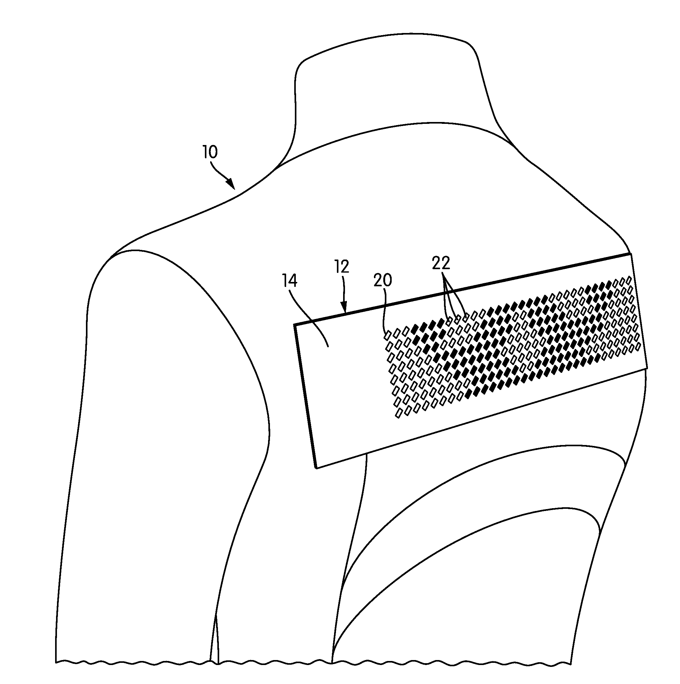
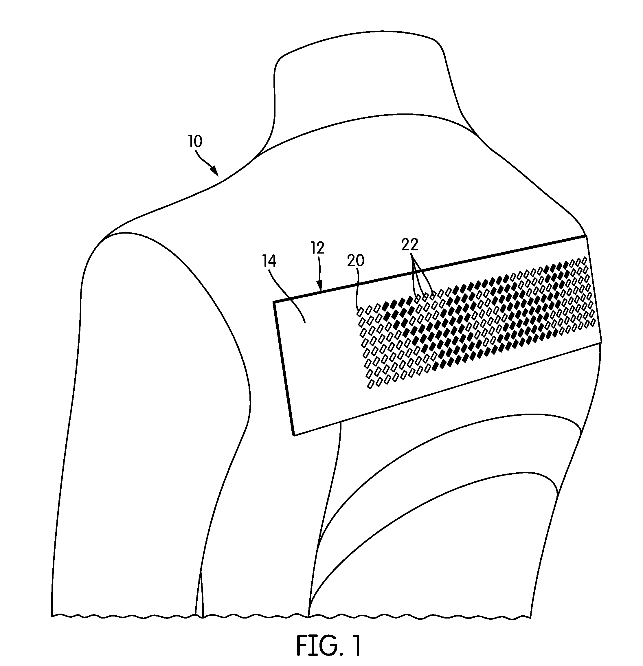
[0037]FIG. 1 is a perspective view of a piece of clothing, generally indicated at 10, according to one embodiment of the invention. The piece of clothing 10 illustrated in FIG. 1 is a jacket or vest, although embodiments of the invention may include any type of clothing. In the illustrated embodiment, a light array 12 is attached to the clothing 10 using hook-and-loop fastener, encapsulated within a fabric pocket 14. In other embodiments, the light array 12 may be sewn or otherwise integrated into the clothing 10. As will be described below in more detail, the light array 12 is an array of light-emitting diodes (LEDs) that are individually logically addressable, such that the array is capable of displaying, words, shapes, patterns, or real-time video. The light array 12 of the illustrated embodiment includes 256 individual LEDs 22, although any number of LEDs 22 may be included.

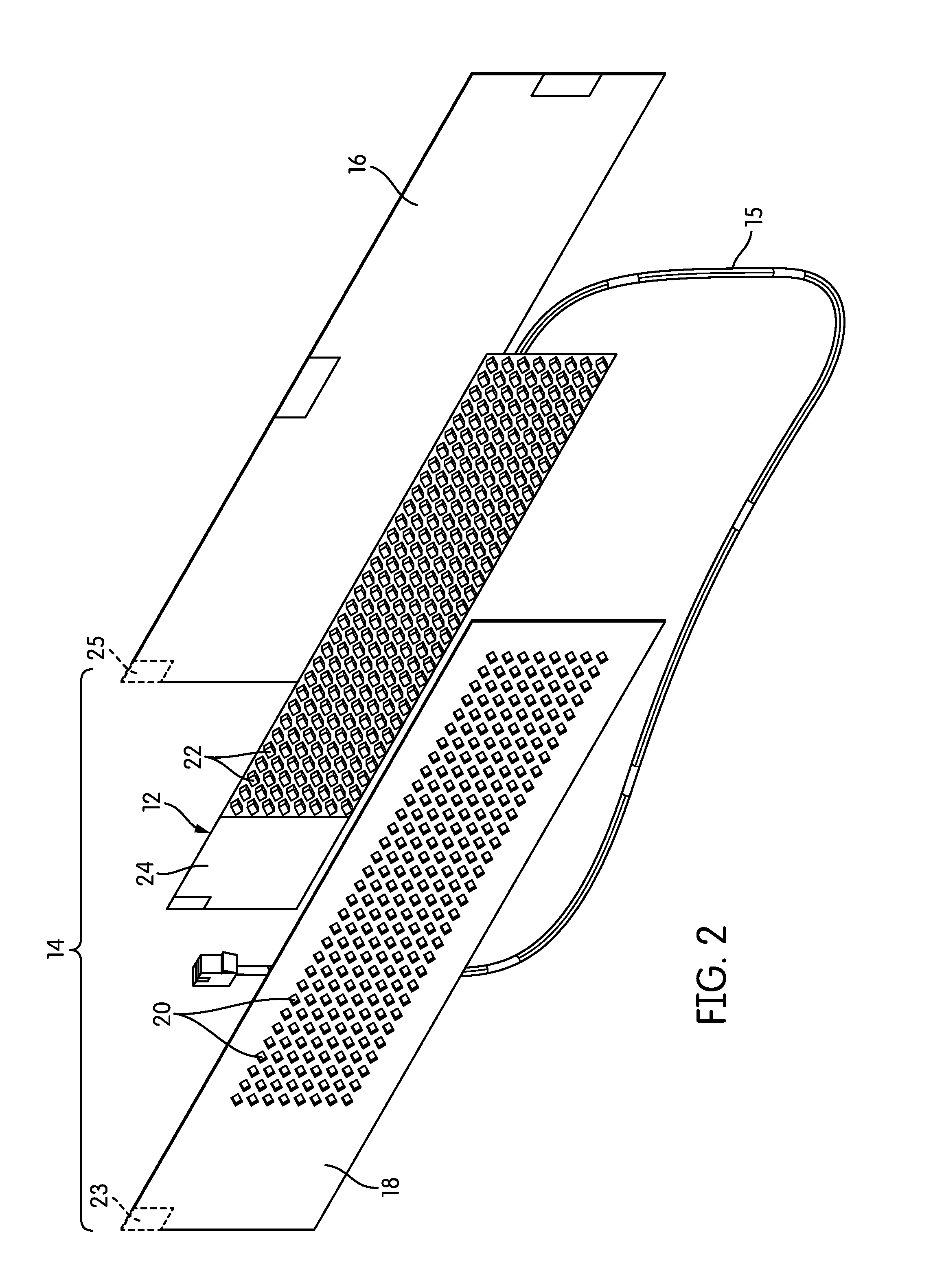
[0038]FIG. 2 is an exploded view of the fabric pocket 14 and light array 12. In this embodiment, the fabri...


PUM


Abstract

Flexible, fabric-encapsulated light arrays particularly suitable for use in clothing are disclosed. The light arrays are light-emitting diode (LED) arrays disposed on flexible printed circuit boards (PCBs). The flexible PCBs include substantially sinusoidal metal contact traces, along which the LEDs are attached at an angle preselected to minimize stresses in the expected directions of bending. The PCBs may also include enlarged metal contact pads and a coverlay arrangement to prevent delamination. The light arrays are contained within pockets that may be made of conductive fabric in order to form a Faraday cage. Systems and methods are also disclosed that use local and wide-area controllers to send words, images, and video to the light arrays substantially in real time.

Description

CROSS-REFERENCE TO RELATED APPLICATIONS[0001]This application claims priority to U.S. Provisional Patent Application No. 61 / 824,876, filed May 17, 2013, the contents of which are incorporated by reference herein in their entirety.[0002]This application is also related to a U.S. patent application entitled “Flexible LED Light Arrays,” given docket no. EG-2-US, and filed on the same date as this application. The contents of that application are incorporated by reference herein in their entirety.BACKGROUND OF THE INVENTION[0003]1. Field of the Invention[0004]The invention relates to clothing with LED light arrays and to systems for displaying video on clothing.[0005]2. Description of Related Art[0006]For many years, manufacturers have sought to incorporate lights into clothing. Most commonly, the lights have been in the form of light-emitting diodes (LEDs). U.S. Pat. No. 4,774,434 to Bennion is one early example of such a design, which includes a number of LEDs arranged on a flexible s...

Claims


Application Information

Patent Timeline
IPC IPC(8): F21V33/00F21V21/14
CPCF21V21/14F21V33/0008F21V33/008F21V23/0435G09F9/33H05K1/0281H05K1/038H05K2201/09263H05K2201/10106F21Y2105/10F21Y2115/10H05K1/189A41D27/085F21V23/005G09F21/023H05B47/19H05B47/00F21V21/002F21Y2101/00F21V23/06F21V23/02G09F2013/222G09F21/02
Inventor NELSON, ANDERS KRISTOFER
Owner EROGEAR
Why Eureka
Try Eureka