Electrical outlet safety device

a safety device and outlet technology, applied in the direction of two-part coupling devices, coupling parts engagement/disengagement, electrical apparatus, etc., can solve the problem of the safety device body expulsion of the plug, and achieve the effect of high resistance and better electrical conta

Active Publication Date: 2014-11-20
KUWAIT UNIV
View PDF27 Cites 17 Cited by
  • Summary
  • Abstract
  • Description
  • Claims
  • Application Information

AI Technical Summary

Problems solved by technology

The thermally conductive blades also transfer heat to a thermal sensor, which causes the body of the safety device to expel the plug in the event that an excessive temperature is reached.

Method used


Image

  • Electrical outlet safety device
  • Electrical outlet safety device
  • Electrical outlet safety device

Examples


Embodiment Construction

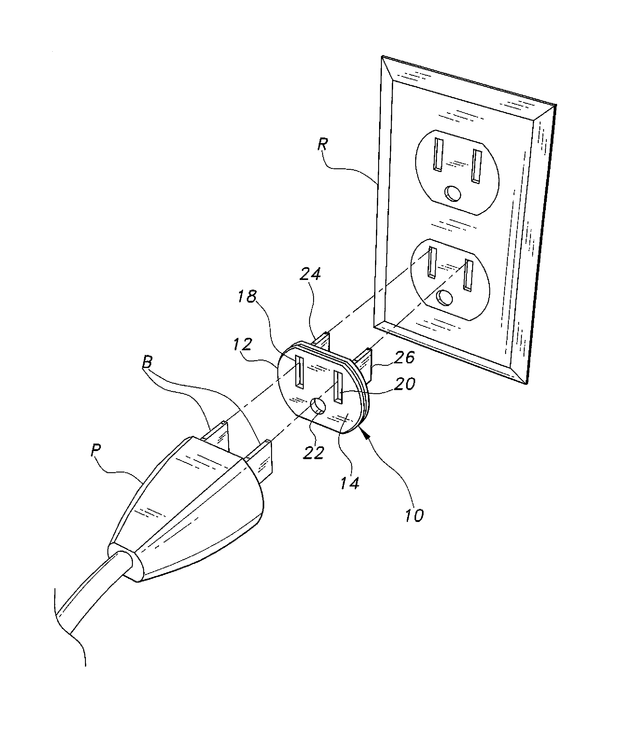
[0017]The electrical outlet safety device is adapted for removable installation between a conventional electrical plug and conventional electrical receptacle or outlet. The safety device provides for the separation of the plug from the outlet in the event that excessively high amperage or resistance and heating occur in the outlet and / or outlet and plug interface.

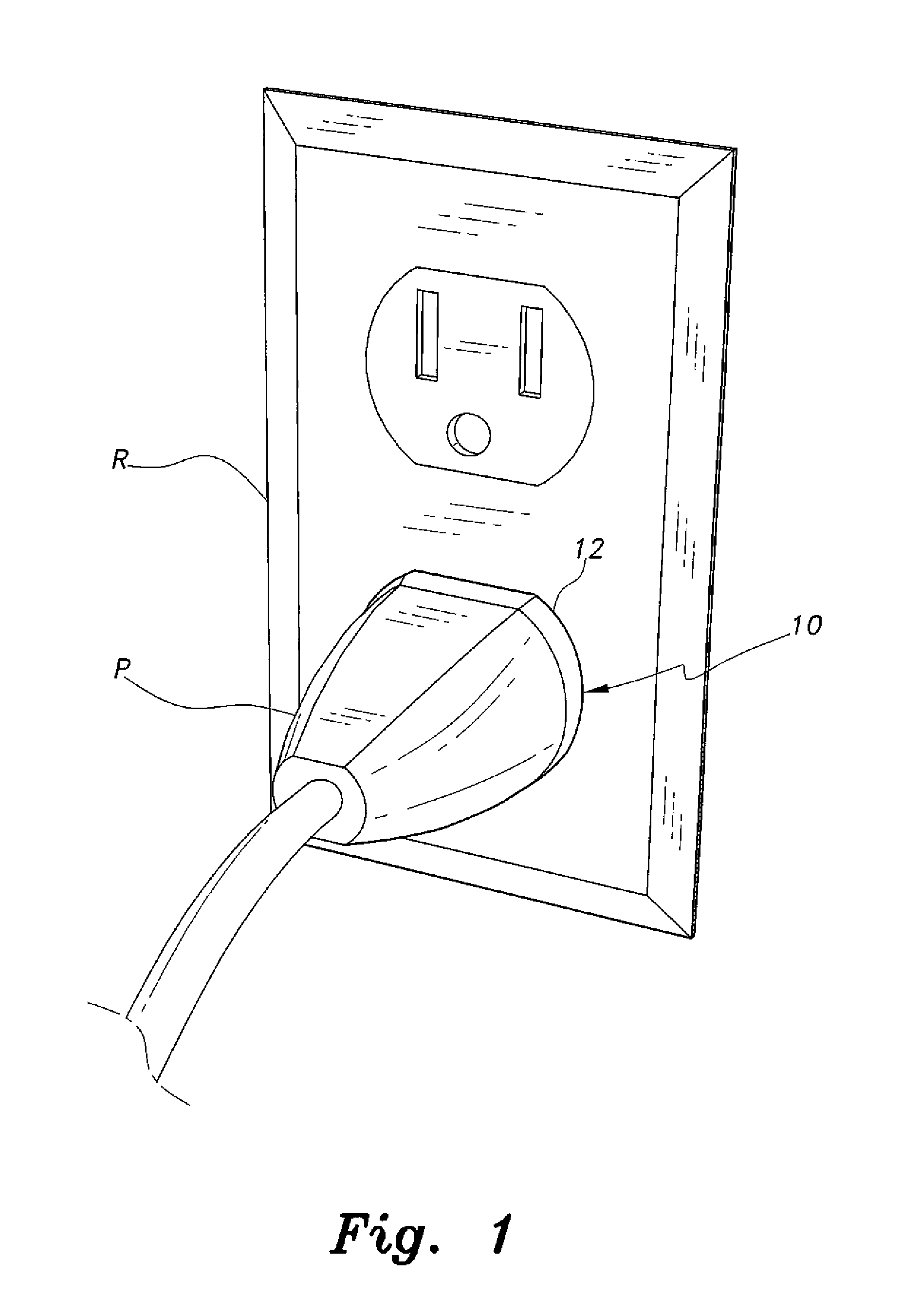
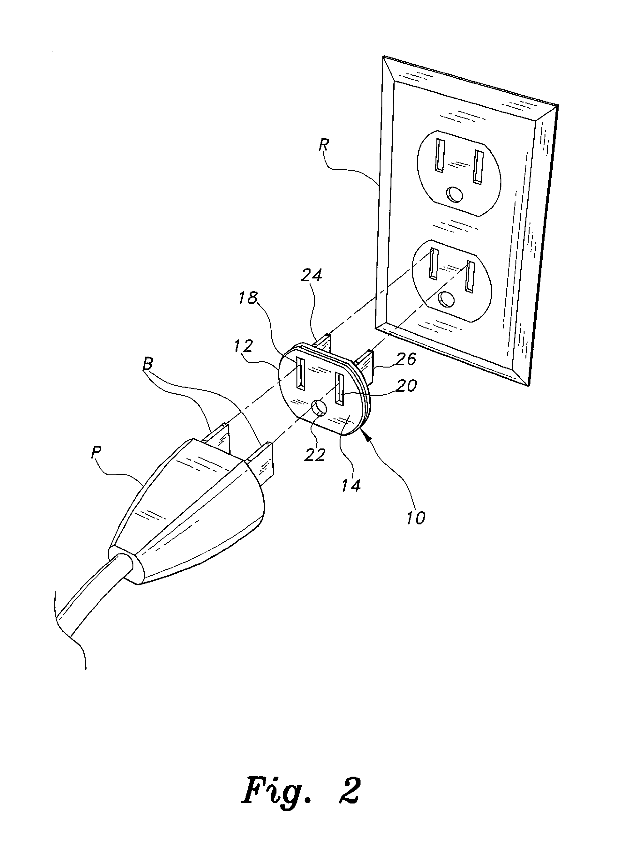
[0018]FIG. 1 of the drawings is an environmental perspective view, showing the electrical outlet safety device 10 installed between a conventional electrical plug P and conventional electrical outlet or receptacle R. FIG. 2 provides an exploded perspective view of the safety device 10, plug P, and receptacle R. The safety device 10 comprises a thin, flat body 12 having a plug face 14, i.e., the face adjacent to the plug P when installed therewith, and an opposite receptacle face 16, i.e., the face adjacent to the receptacle R when installed therewith, as shown in profile in FIG. 3. The body 12 of the safety device 10 is pre...


PUM


Abstract

The electrical outlet safety device is placed between an electrical plug and the corresponding electrical outlet or receptacle to which the plug is connected. The safety device includes a thin body portion formed of a material adapted to expand rapidly if exposed to a predetermined temperature. A series of thin, electrically and thermally conductive blades extends from the body, with the blades being captured between the prongs of the plug and the internal contacts of the receptacle when installed therewith. If excessively high electrical resistance and correspondingly high temperature are produced in one or more of the electrical connections between the plug and the outlet, the blades of the safety device transmit the excessive temperature to the body, whereupon the body is transformed to an expansive electrically insulating foam that expels the plug from the receptacle. Springs may be included within the body to provide additional expansive force.

Description

BACKGROUND OF THE INVENTION[0001]1. Field of the Invention[0002]The present invention relates generally to electrical distribution systems, and particularly to an electrical outlet safety device that automatically separates an electrical plug or the like from an electrical receptacle or outlet in the event that excessive electrical current flows through the plug and receptacle.[0003]2. Description of the Related Art[0004]The modern world is becoming ever more dependent upon various electrical and electronic devices for use both in the home and in the workplace. Nearly all contemporary structures include extensive electrical systems configured to supply any reasonable need for electrical power to a number of built-in and portable electrical devices and appliances installed and placed in the structures.[0005]The design of electrical systems to provide a safe supply of electrical energy for anticipated electrical loads is a well-established field. As long as the electrical loads are ma...

Claims


Application Information

Patent Timeline
Patent Type & Authority Applications(United States)
IPC IPC(8): H01R13/66H01R13/635
CPCH01R13/635H01R13/6683H01R13/6666H01R13/7132H01R24/30H01R24/78H01R31/065
Inventor AL-ANZI, BADER SHAFAQA
Owner KUWAIT UNIV
Why Eureka
Try Eureka