Bone anchoring member with clamp mechanism

a technology of bone anchoring and clamping mechanism, which is applied in the field of spinal disorders, can solve the problems of complicated plate placement, secure placement and alignment of rod between pedicle screws, and the difficulty of fixing the plate between two or more firmly implanted screws

Inactive Publication Date: 2014-11-20
ELIASEN KENNETH ARDEN +2
View PDF5 Cites 25 Cited by
  • Summary
  • Abstract
  • Description
  • Claims
  • Application Information

AI Technical Summary

Benefits of technology

[0010]Accordingly, there is provided a pedicle screw for insertion into the pedicle portion of a vertebra and having at its exposed end a threaded rod connected in a generally parallel orientation to the longitudinal axis of the pedicle screw but laterally offset from the longitudinal axis of the pedicle screw. The threaded rod may be secured directly to the screw but is preferable provided with a collar that is captured by an enlarged screw head to seat, orient and retain the threaded rod in position. A locking arm and retaining nut are provided over the threaded rod for affixing a spinal rod to the pedicle screw substantially over and aligned with the longitudinal axis of the screw. A yoke may be provided in the collar also to receive and secure the rod. An alternate cap and clamping elements enable the incorporation of cross links between multiple screws and / or rods.

Problems solved by technology

The secure placement and alignment of a rod between pedicle screws or the placement of a plate linking two or more firmly implanted screws can be complicated by spinal geometry and the angular orientation of the screws and exacerbated by any deformity of the spinal column.

Method used


Image

  • Bone anchoring member with clamp mechanism
  • Bone anchoring member with clamp mechanism
  • Bone anchoring member with clamp mechanism

Examples


Embodiment Construction

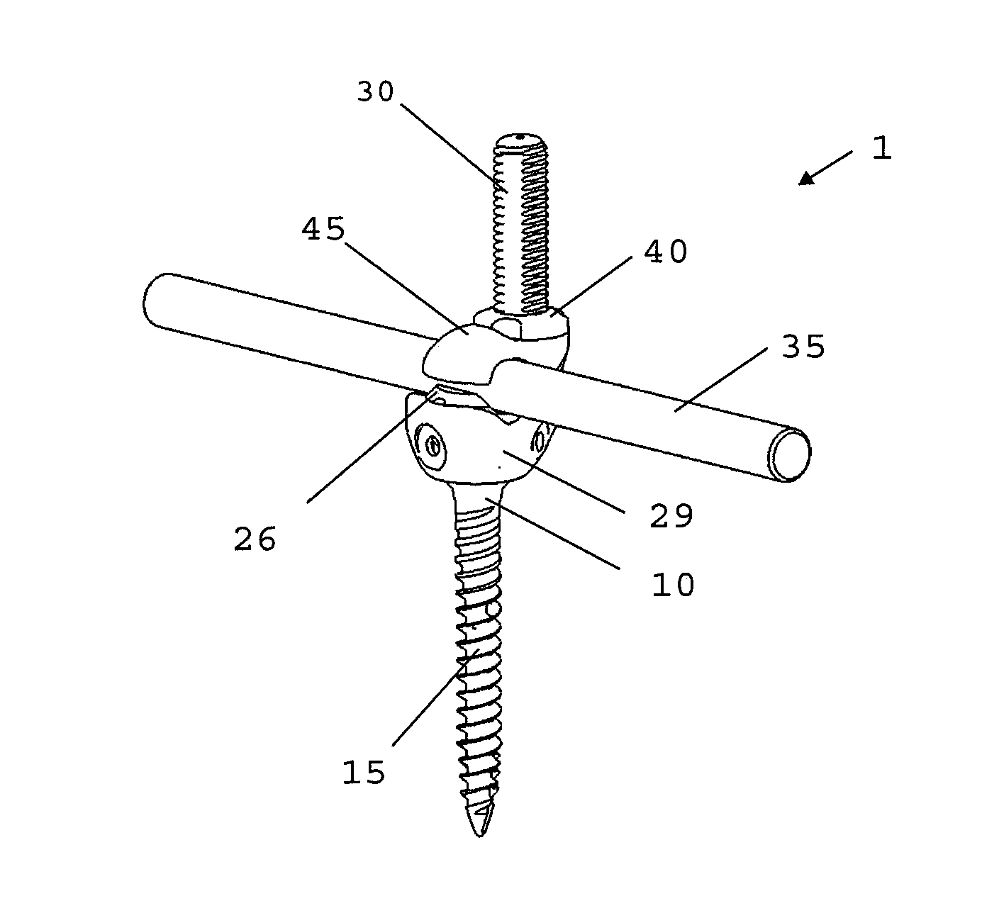
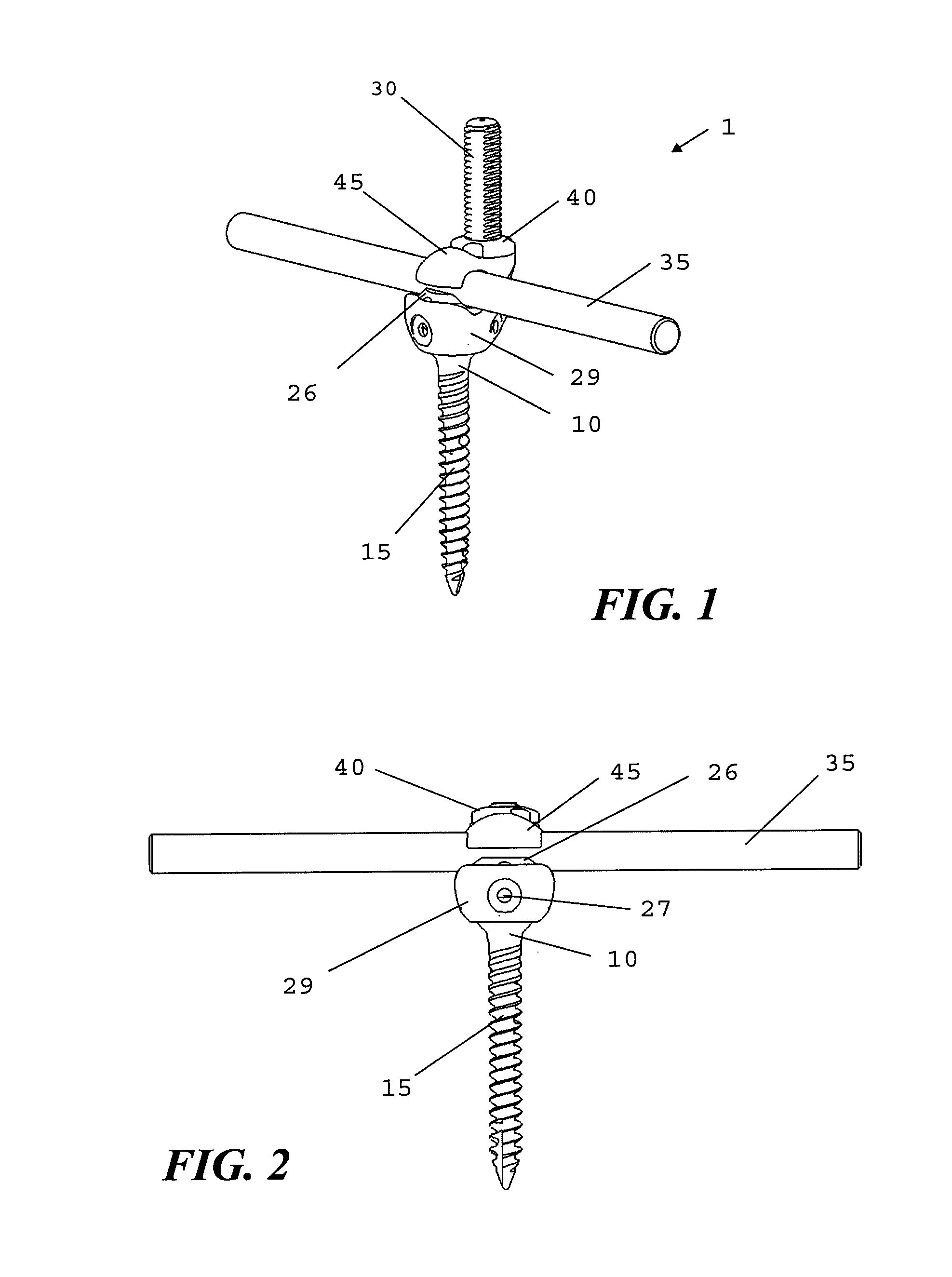
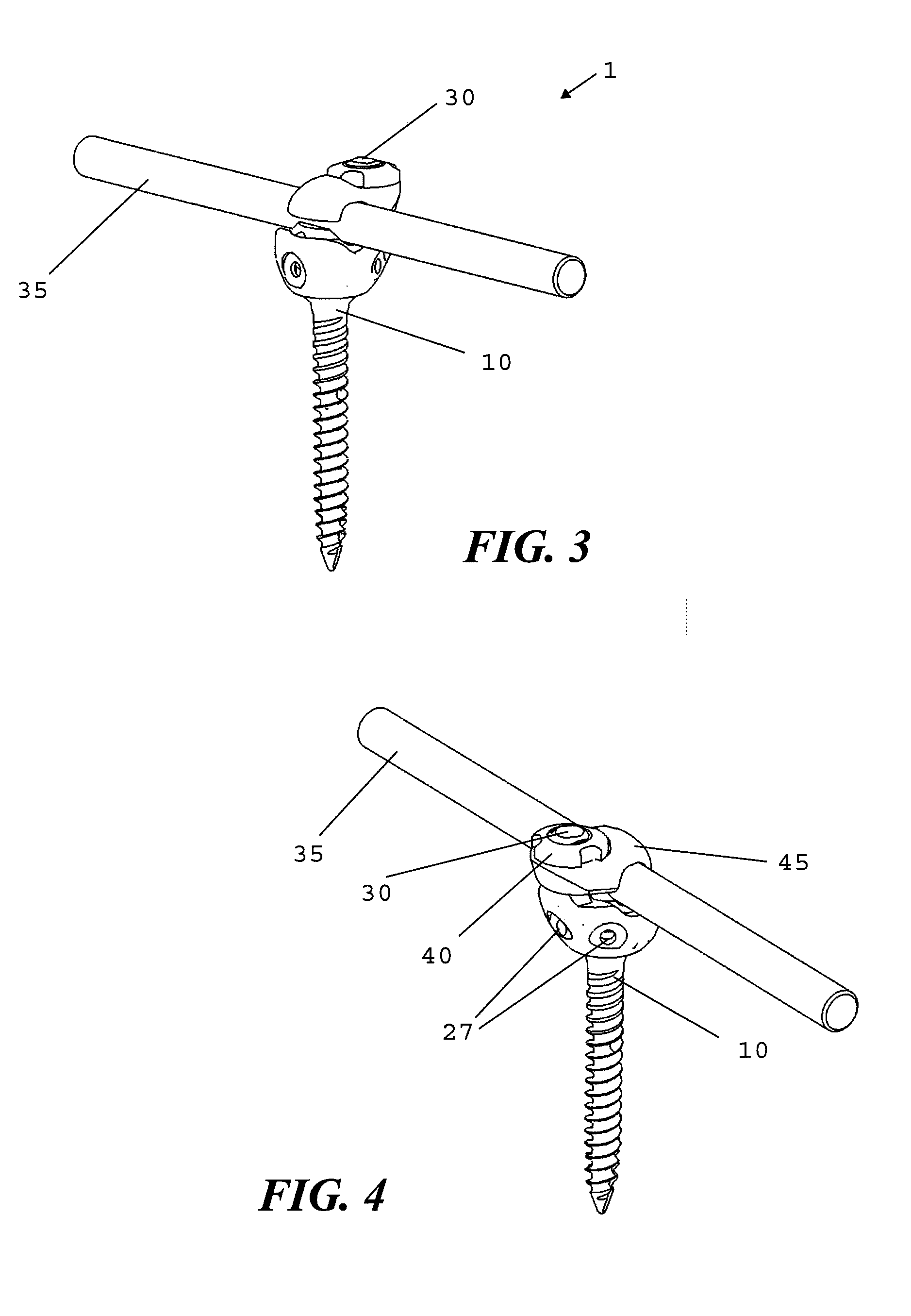
[0044]With reference to FIGS. 1-6, a preferred embodiment of the present invention 1 comprises a pedicle screw 10 for insertion into the pedicle portion of a vertebra and having at its exposed end a threaded rod or stem 30 connected in a generally parallel orientation to, but laterally offset from, the longitudinal axis of the pedicle screw 10. It is observed that for purposes of this application the longitudinal axis of the pedicle screw 10 is defined as the vertical axis and references to the vertical are made with respect to this axis. The figures provided herewith generally depict the pedicle screw on the vertical axis although it is, of course, understood that the axis of the pedicle screw is unlikely to be vertical one implanted in the vertebra of a patient. Thus, the stem 30 is substantially vertical when connected to the pedicle screw 10. The stem 30 is preferable provided as part of a cup assembly 29 that is captured by an enlarged head of screw 10 and may include a yoke 26...


PUM


Abstract

A multi-piece disc replacement implant for replacing a disc removed by a discectomy including an upper plate member, a lower plate member, and an intermediate resilient member providing movement between te two plate members replicating the natural movement of the spine. The plate members are rigid and have orthogonal sidewalls forming an enclosure. The resilient member is an elastic solid or a multi-chamber balloon structure of fluid-filled sacks that collectively define a non-uniform shape such as an oblate spheroid, or a helically coiled string of beads. Such an implant is capable of supporting the compressive and cyclic loads required of a natural disc. The upper and lower plate members are cooperatively formed to selectively limit the allowable range of motion in any given direction and a provided with protrusions to be received in one or more channels cooperatively formed in the vertebrae and secured in place by a bone screw.

Description

CROSS-REFERENCE TO RELATED APPLICATIONS[0001]The present application is a continuation of co-pending U.S. patent application Ser. No. 12 / 653,086 for a “Bone Anchoring Member With Clamp Mechanism” filed Dec. 8, 2009 from which priority is derived and which is incorporated herein by reference. U.S. patent application Ser. No. 12 / 653,086 is itself a continuation-in-part of U.S. patent application Ser. No. 12 / 462,127 for “Bone Anchoring Member” filed Jul. 29, 2009 which is also incorporated herein by reference and which derives priority from U.S. provisional application 61 / 137,255 filed on Jul. 29, 2008 which is further incorporated herein by reference.BACKGROUND OF THE INVENTION[0002]1. Field of the invention[0003]The present invention relates generally to devices and methods for treating spinal disorders and more specifically to a fixation assembly for retaining vertebrate endoskeletal members in a desired fixed spatial relationship.[0004]2. Description of the Background[0005]A variet...

Claims


Application Information

Patent Timeline
Patent Type & Authority Applications(United States)
IPC IPC(8): A61B17/70
CPCA61B17/705A61B17/7034A61B17/7037A61B17/7049A61B17/7052
Inventor ELIASEN, KENNETH ARDENETTLINGER, MARKAFLATOON, KAMRAN
Owner ELIASEN KENNETH ARDEN
Why Eureka
Try Eureka