
Shift device

a technology of shifting device and shift lever, which is applied in the direction of gearing control, mechanical equipment, transportation and packaging, etc., can solve the problems of misalignment affecting the positioning accuracy of the center pivot of the shift lever toward the shift direction, etc., and achieves the effect of improving the positioning accuracy of the center pivot of the operating member and simple configuration

Active Publication Date: 2014-11-27
KK TOKAI RIKA DENKI SEISAKUSHO
View PDF4 Cites 12 Cited by
  • Summary
  • Abstract
  • Description
  • Claims
  • Application Information

AI Technical Summary

Benefits of technology

The present invention is a shift device that improves the positioning accuracy of the center of pivot of an operating member. This is achieved by integrating a supporting shaft or a supporting hole into the operating member and the supporting member, respectively, and inserting the supporting shaft into the supporting hole from the axial direction. Additionally, the invention includes a detection section that detects the pivoting position of the operating member, further improving the accuracy of the center of pivot positioning. The shift device can also have a slide section that presses and slides the operating member to facilitate easy insertion of the supporting shaft into the supporting hole. Overall, the invention allows for improved functioning and performance of the shift device.

Problems solved by technology

As a result, the positioning accuracy of the center of pivot of the shift lever toward the select direction is affected by the assembly margin of error of the select rotation shaft to the shift rotation shaft.
As a result, the positioning accuracy of the center of pivot of the shift lever toward the shift direction is affected by misalignment when the pair of semicircular arc faces are combined, due to assembly margin of error of the upper side bracket and the lower side bracket.

Method used


Image

  • Shift device
  • Shift device
  • Shift device

Examples


Embodiment Construction

Exemplary Embodiment Configuration

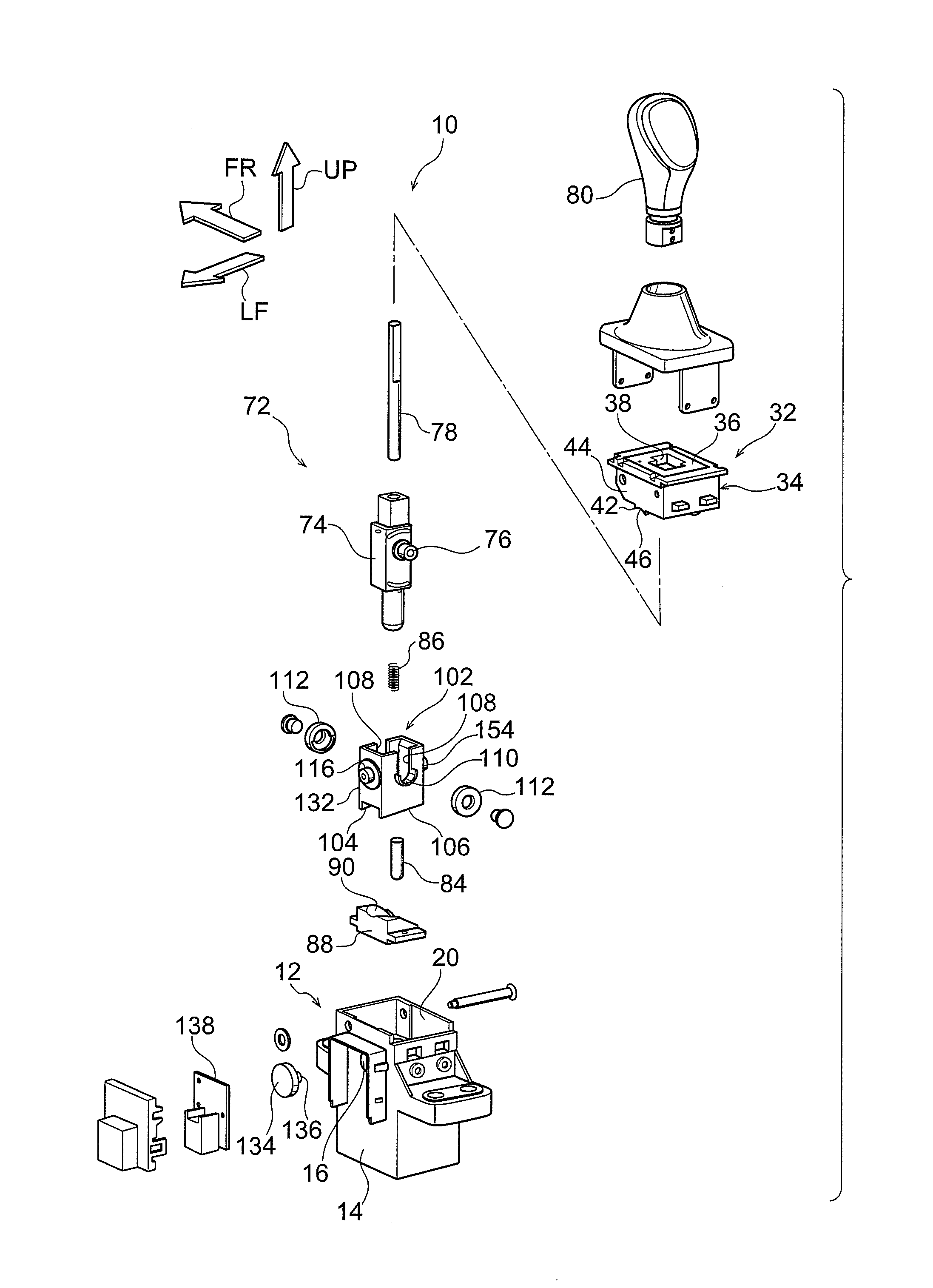
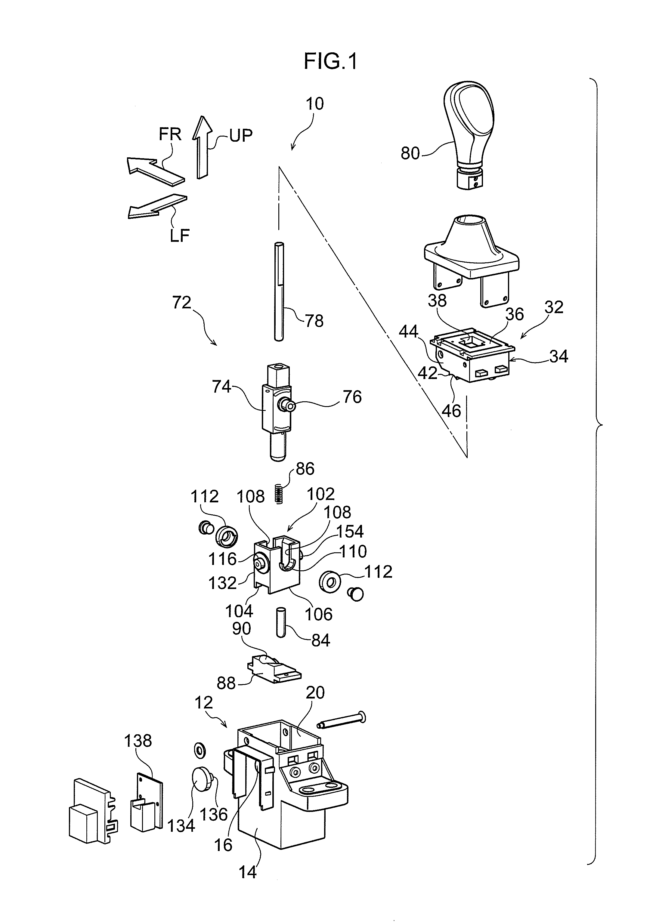
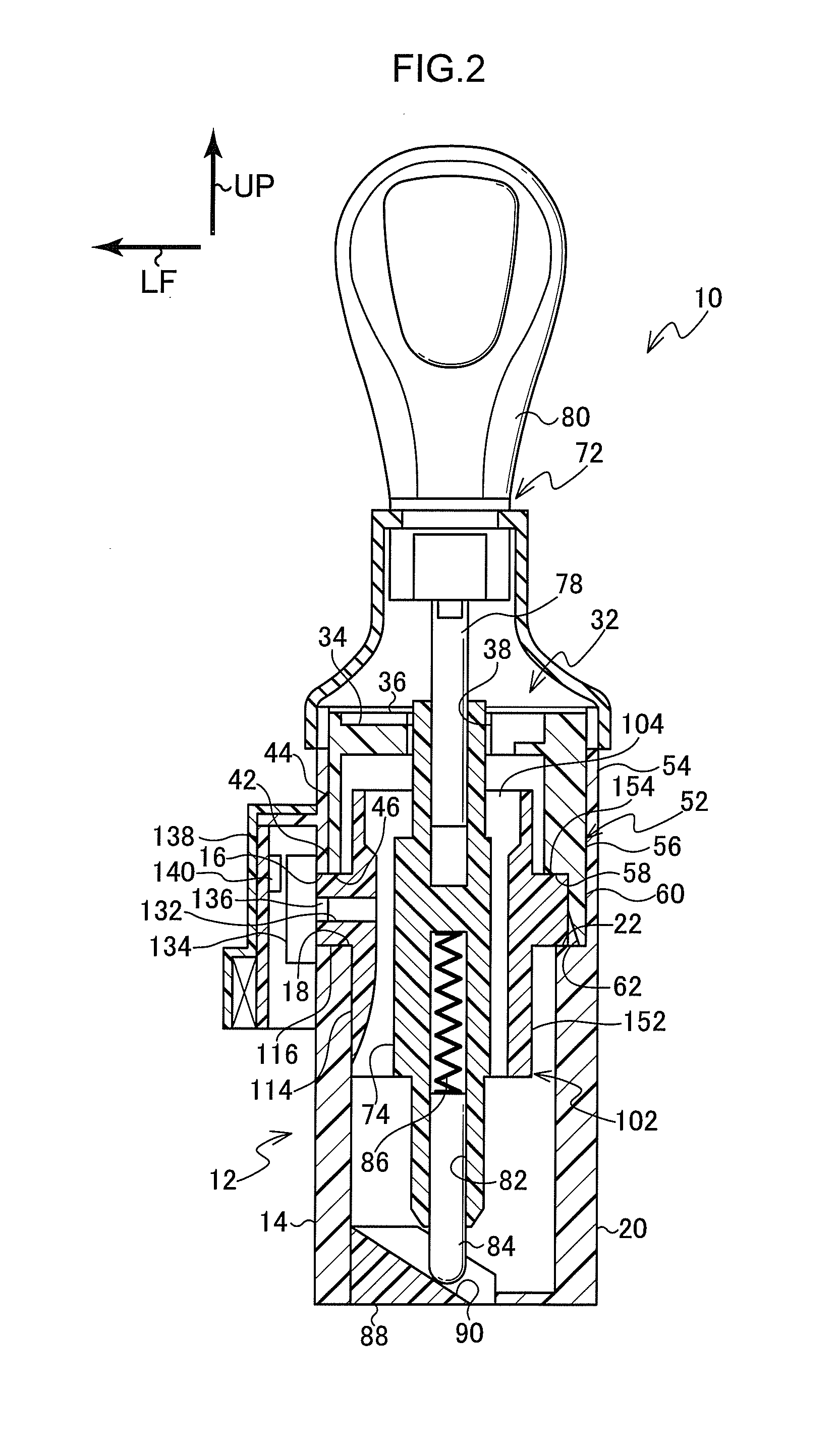
[0031]Explanation follows regarding a shift lever device 10 as a shift device according to an exemplary embodiment of the present invention, with reference to FIG. 1 to FIG. 10. Note that in FIG. 1 to FIG. 10, an arrow FR indicates to the shift lever device 10 front, an arrow LF indicates to the shift lever device 10 left, and an arrow UP indicates upward of the shift lever device 10. However, the front-rear direction, left-right direction and up-down direction of the shift lever device 10 may be the same as, or may be different to, the respective front-rear direction, left-right direction and up-down direction of a vehicle installed with the shift lever device 10. Moreover, the shift lever device 10 is provided for example to a floor or an instrument panel of a vehicle.

[0032]As illustrated in FIG. 1 and FIG. 2, the shift lever device 10 is equipped with a shift lever plate 12 as a supporting member. The shift lever plate 12 is formed as rectangular...


PUM


Abstract

The present invention provides a shift device capable of improving positioning accuracy of a center of pivot of an operating member. In a shift lever device, a supporting shaft is formed to a retainer, and a supporting hole is formed to a shift lever plate. Furthermore, by sliding the retainer in the support shaft axial direction with respect to the shift lever plate, the supporting shaft is inserted into the supporting hole, and the shift lever plate is supported by the retainer so as to be capable of pivoting. Positioning accuracy of the supporting shaft 116 with respect to the retainer, and positioning accuracy of the supporting hole 16 with respect to the shift lever plate can be increased as a result. The positioning accuracy of the center of pivot of the retainer is thereby capable of being improved.

Description

CROSS-REFERENCE TO RELATED APPLICATION[0001]This application claims priority under 35 USC 119 from Japanese Patent Application No. 2013-110140 filed May 24, 2013, the disclosure of which is incorporated by reference herein.BACKGROUND[0002]1. Technical Field[0003]The present invention relates to a shift device in which a vehicle transmission is operated by operating an operating member.[0004]2. Related Art[0005]In a shift lever device described in Japanese Patent Application Laid-Open (JP-A) No. 2008-132932, a select rotation shaft of a shift rotation shaft is passed through a shift lever, and the shift lever is thereby supported by the shift rotation shaft so as to be capable of pivoting in a select direction.[0006]Furthermore, a rotation supporting portion of the shift rotation shaft is inserted into a shaft bearing face of a base bracket, and the shift lever is thereby supported by the base bracket so as to be capable of pivoting in the shift direction.[0007]In the shift lever dev...

Claims


Application Information

Patent Timeline
Patent Type & Authority Applications(United States)
IPC IPC(8): F16H59/10
CPCF16H59/105F16H59/10F16H61/24F16H2059/0273F16H2061/243F16H2061/247Y10T74/2014
Inventor YAMAMOTO, MAKOTO
Owner KK TOKAI RIKA DENKI SEISAKUSHO
Learn More