Eureka AIR delivers breakthrough ideas for toughest innovation challenges, trusted by R&D personnel around the world.

Work machine and automatic control method for blade of work machine

Inactive Publication Date: 2014-11-27
KOMATSU LTD
View PDF13 Cites 7 Cited by
  • Summary
  • Abstract
  • Description
  • Claims
  • Application Information

AI Technical Summary

Benefits of technology

The work machine described in the patent can use sensors to restore the blade to its original position, preventing it from digging into the ground surface too much or being too far from it. This results in more effective excavation work.

Problems solved by technology

Since stroke sensors are generally expensive, there is a desire to recognize the blade attitude with, for example, only two stroke sensors for detecting the stroke amount of the pair of lift cylinders.
However, the degree of the tilt of the blade forward, backward, left or right cannot be recognized on the basis of only the stroke amount of the pair of lift cylinders.
As a result, excavation work cannot be conducted effectively if excavation work is conducted without controlling the attitude of the blade.
Specifically, even if the blade is lifted to a standard height, the cutting edge of the blade may dig into the ground surface and excavate too much earth if the blade is pitched forward too much.
Conversely, even when the blade is lifted to the standard height, the cutting edge may be too far removed from the ground surface so that not enough earth is excavated if the blade is pitched backward too much.

Method used


Image

  • Work machine and automatic control method for blade of work machine
  • Work machine and automatic control method for blade of work machine
  • Work machine and automatic control method for blade of work machine

Examples


first embodiment

Configuration of Bulldozer 100

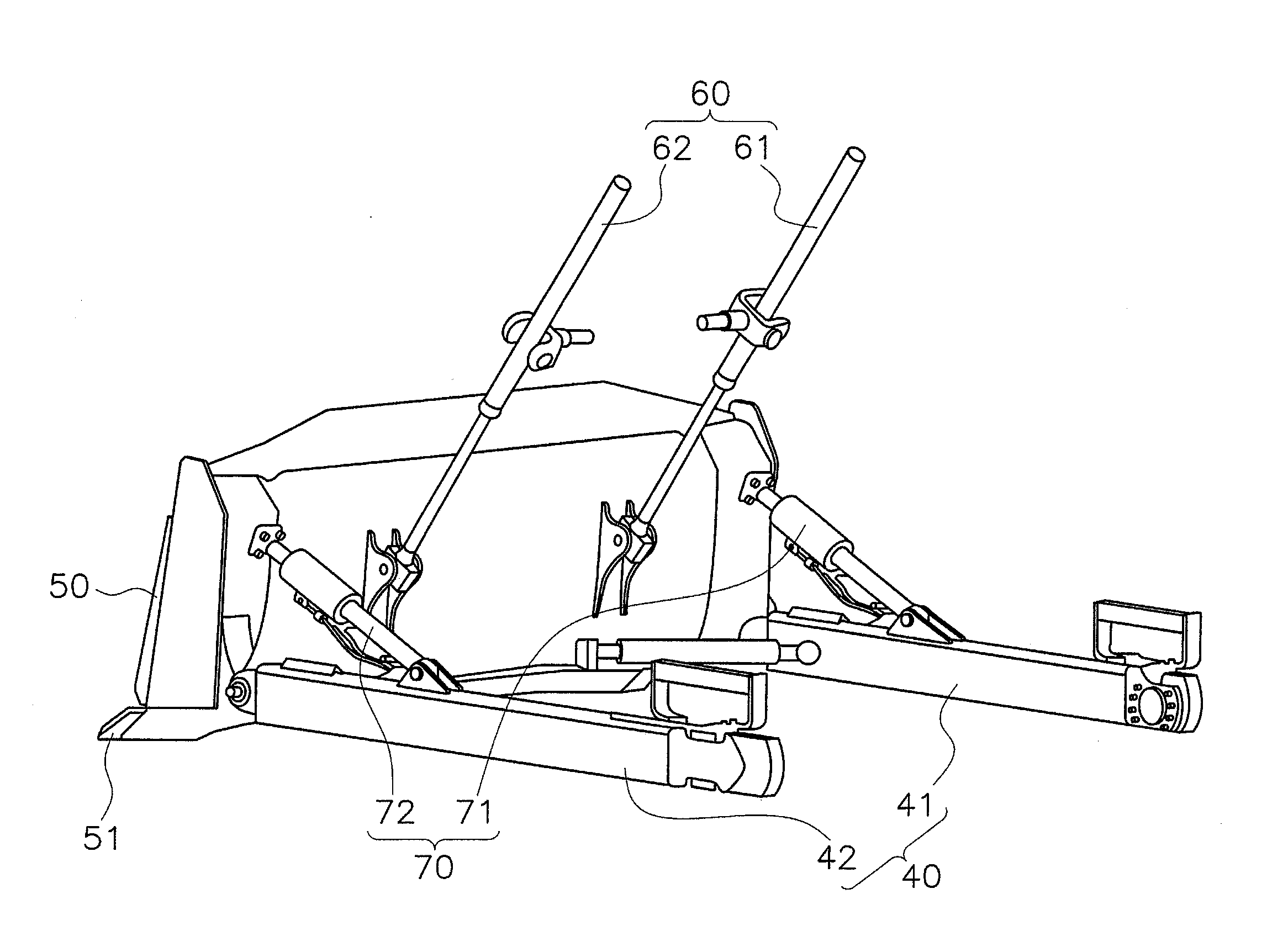
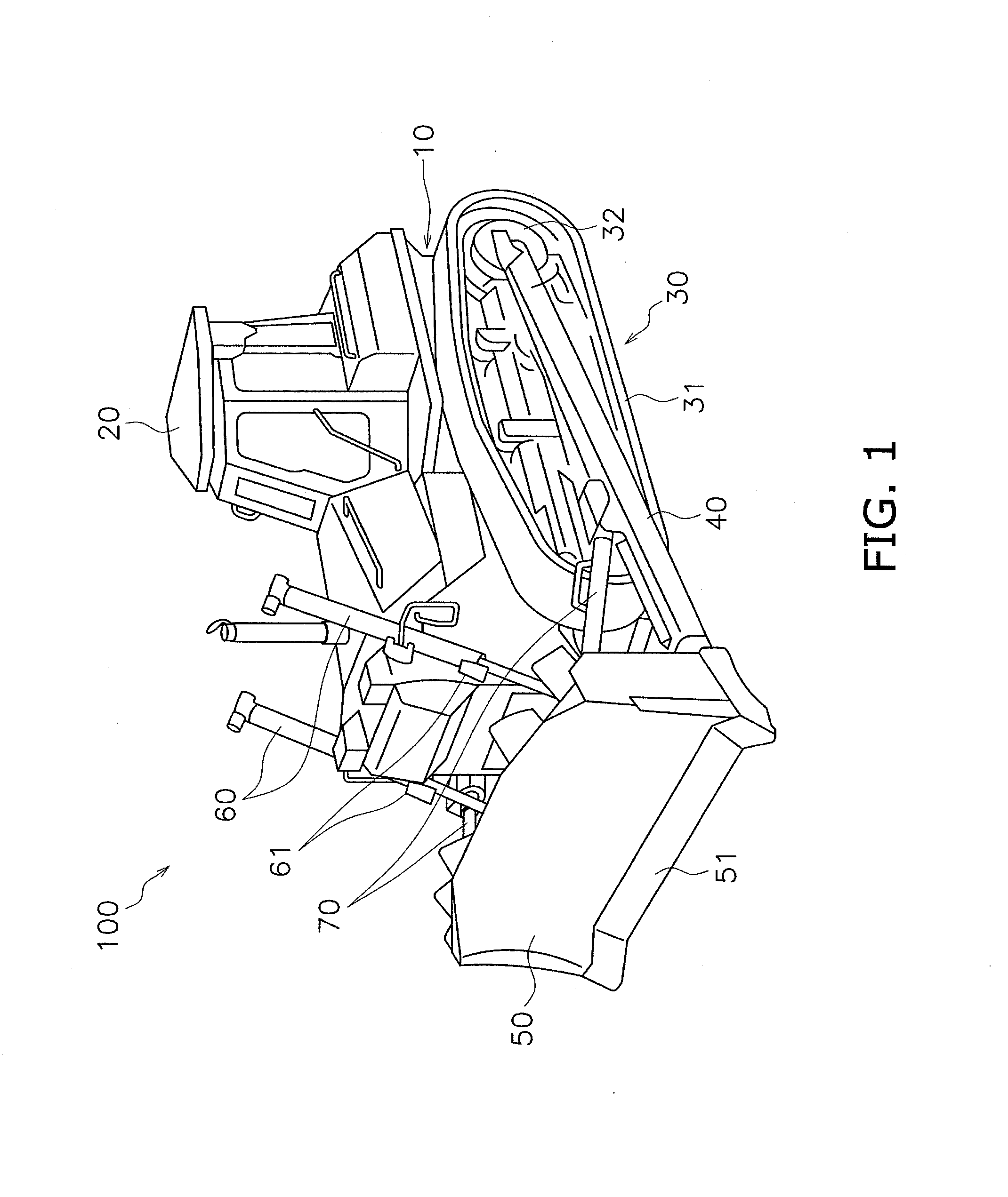
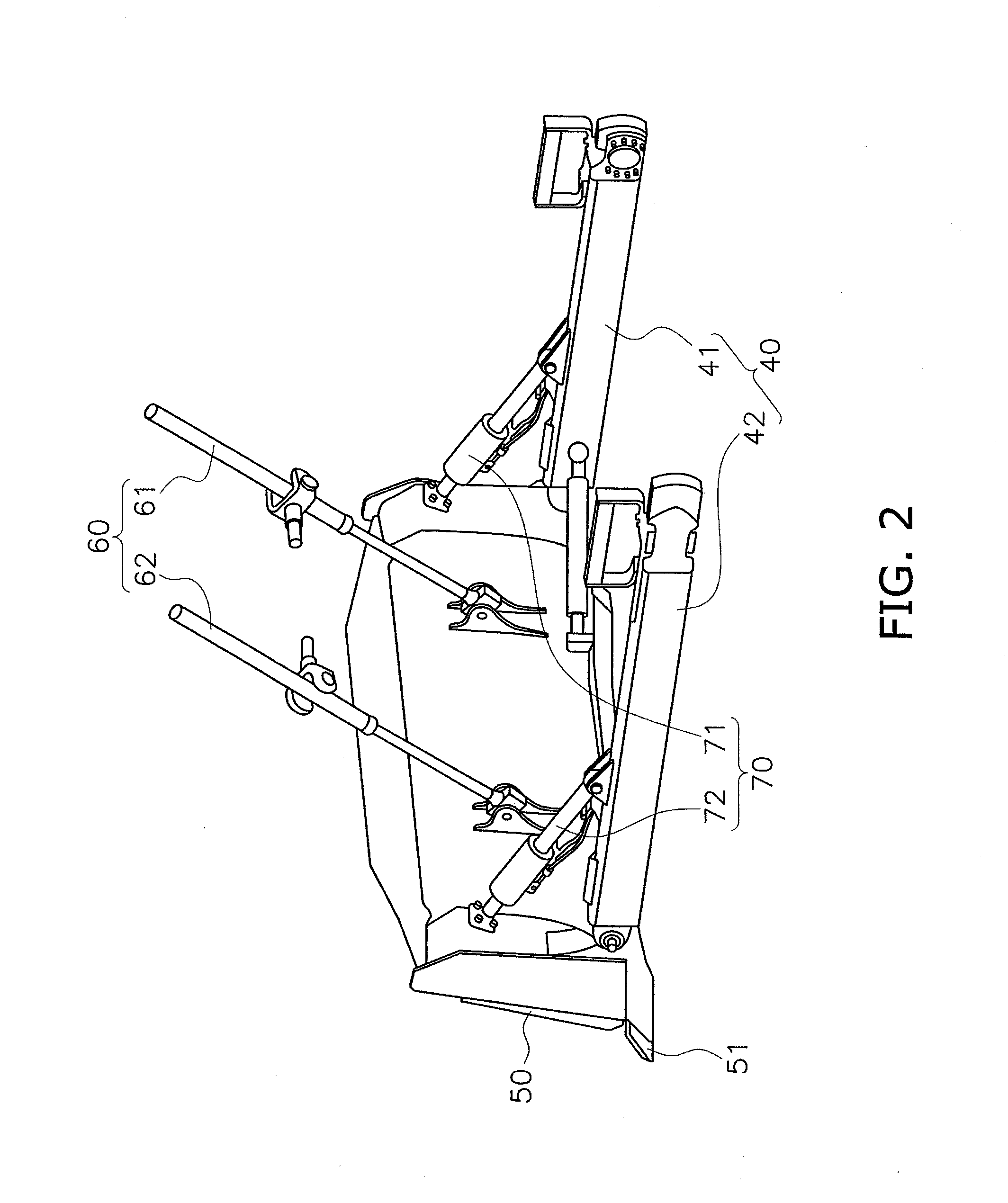
[0038]FIG. 1 is a front perspective view of a configuration of a bulldozer 100. FIG. 2 is a rear perspective view of a configuration of an actuation system for a blade 50.

[0039]The bulldozer 100 is equipped with a vehicle body 10, a cab 20, a travel device 30, a pair of lift frames 40, the blade 50, a pair of lift cylinders (first hydraulic cylinders) 60, and a pair of pitch / tilt cylinders (second hydraulic cylinders) 70. The bulldozer 100 includes a blade control system 200 (see FIG. 4) for automatically controlling an attitude of the blade 50. The blade control system 200 will be discussed below.

[0040]The vehicle body 10 supports the cab 20. The vehicle body 10 is supported by the travel device 30. The cab 20 includes a driver's seat for an operator to sit in, and pedals and levers for operating the travel device 30 and the blade 50. In particular, a blade attitude restore button 210 (see FIG. 4) for restoring the attitude of the blade 50 to a referen...

second embodiment

[0074]The following is an explanation of a bulldozer according to a second embodiment. The differences between the second embodiment and the first embodiment lie in the configuration of the pair of pitch / tilt cylinders and in the blade attitude restoration method. Therefore, the differences between the first and second embodiments will be mainly discussed below.

Configuration of Pair of Pitch / Tilt Cylinders 70A

[0075]A pair of pitch / tilt cylinders 70A according to the second embodiment includes a right pitch cylinder 73 and a left pitch / tilt cylinder 74. FIG. 7A is a schematic view of a configuration of the right pitch cylinder 73. FIG. 7B is a schematic view of a configuration of the left pitch / tilt cylinder 74. The states of each cylinder when the blade 50 is moved to the reference attitude are illustrated in FIGS. 7A and 7B.

[0076]As illustrated in FIGS. 7A and 7B, the right pitch cylinder 73 and the left pitch / tilt cylinder 74 have the same configurations. Specifically, a cylinder ...


PUM


Abstract

A work machine includes a vehicle body, a blade supported by the vehicle body, a pair of first hydraulic air of second hydraulic cylinders, a pair of lift stroke sensors and a control unit. The first hydraulic cylinders are configured to lower and raise the blade. The second hydraulic cylinders are configured to tilt the blade forward and backward and left and right. The lift stroke sensors are configured to detect stroke amounts from the pair of first hydraulic cylinders, respectively. The control unit is configured to start actuating the pair of second hydraulic cylinders when the stroke amounts of the pair of first hydraulic cylinders match. The control unit is configured to stop actuating the pair of second hydraulic cylinders based on a magnitude relation between a prescribed threshold and a difference in the stroke amounts of the pair of first hydraulic cylinders.

Description

CROSS-REFERENCE TO RELATED APPLICATIONS[0001]This application is a U.S. National stage application of International Application No. PCT / JP2013 / 066214, filed on Jun. 12, 2013. This U.S. National stage application claims priority under 35 U.S.C. §119(a) to Japanese Patent Application No. 2012-174436, filed in Japan on Aug. 6, 2012, the entire contents of which are hereby incorporated herein by reference.FIELD OF THE INVENTION[0002]The present invention relates to a work machine provided with a blade and an automatic control method for the blade of the same.BACKGROUND INFORMATION[0003]A work machine such as a bulldozer or a motor grader is equipped with a blade as work implement for excavating earth.[0004]US Patent Application Publication No. 2005 / 0065689 discloses a work machine equipped with a pair of lift cylinders for lowering and raising the blade, and a pair of pitch / tilt cylinders for pitching the blade forward and backward. The work machine of US Patent Application Publication ...

Claims


Application Information

Patent Timeline
IPC IPC(8): E02F3/84E02F3/76
CPCE02F3/844E02F3/7618E02F3/7613E02F3/847
Inventor NAKATA, KAZUSHIYAMAMOTO, SHIGERU
Owner KOMATSU LTD
Why Eureka
Eureka Blog
Learn More