Mobile Conducting Unit for a Breaker, Including a Spring for Accelerating the Separation of Arc Contacts

Inactive Publication Date: 2014-11-27
ALSTOM TECH LTD
View PDF4 Cites 17 Cited by
  • Summary
  • Abstract
  • Description
  • Claims
  • Application Information

AI Technical Summary

Benefits of technology

[0022]However, the particular design as described above departs from conventional drive devices of the prior art by providing for the connection point to move in translation at a constant speed during an opening operation and during a closing operation of the switchgear. In this example, the mechanical system makes it possible to effectively vary the speed the connection point moves in translation during one and/or the other of these operations. Consequently, this controlled variation may be determined in such a manner as to limit as far as possible mechanical and electrical wear of the electrically conductive unit. For the opening operation, this possible variation is added to the specific variation of the present invention, which var

Problems solved by technology

During those repeatedly-performed operations, the conductive unit, which generally takes the form of a cylinder fitted with a main contact and with an arcing contact, is subjected to mechanical and electrical stresses that gradually cause it to deteriorate.
Those problems generate the creation of particles, of pollution, and of heat, and affect the lifetime of the switchgear.
In particular, during an opening operation, if the speed of the electrically conductive unit is too fast, it leads to mechanical wear of the main contacts.
That might suggest reducing the speed of the electrically conductive unit, but doing so would result in the arcing contacts becoming worn.
Nevertheless, the stationary arcing contact can no longer really

Method used


Image

  • Mobile Conducting Unit for a Breaker, Including a Spring for Accelerating the Separation of Arc Contacts
  • Mobile Conducting Unit for a Breaker, Including a Spring for Accelerating the Separation of Arc Contacts
  • Mobile Conducting Unit for a Breaker, Including a Spring for Accelerating the Separation of Arc Contacts

Examples


Embodiment Construction

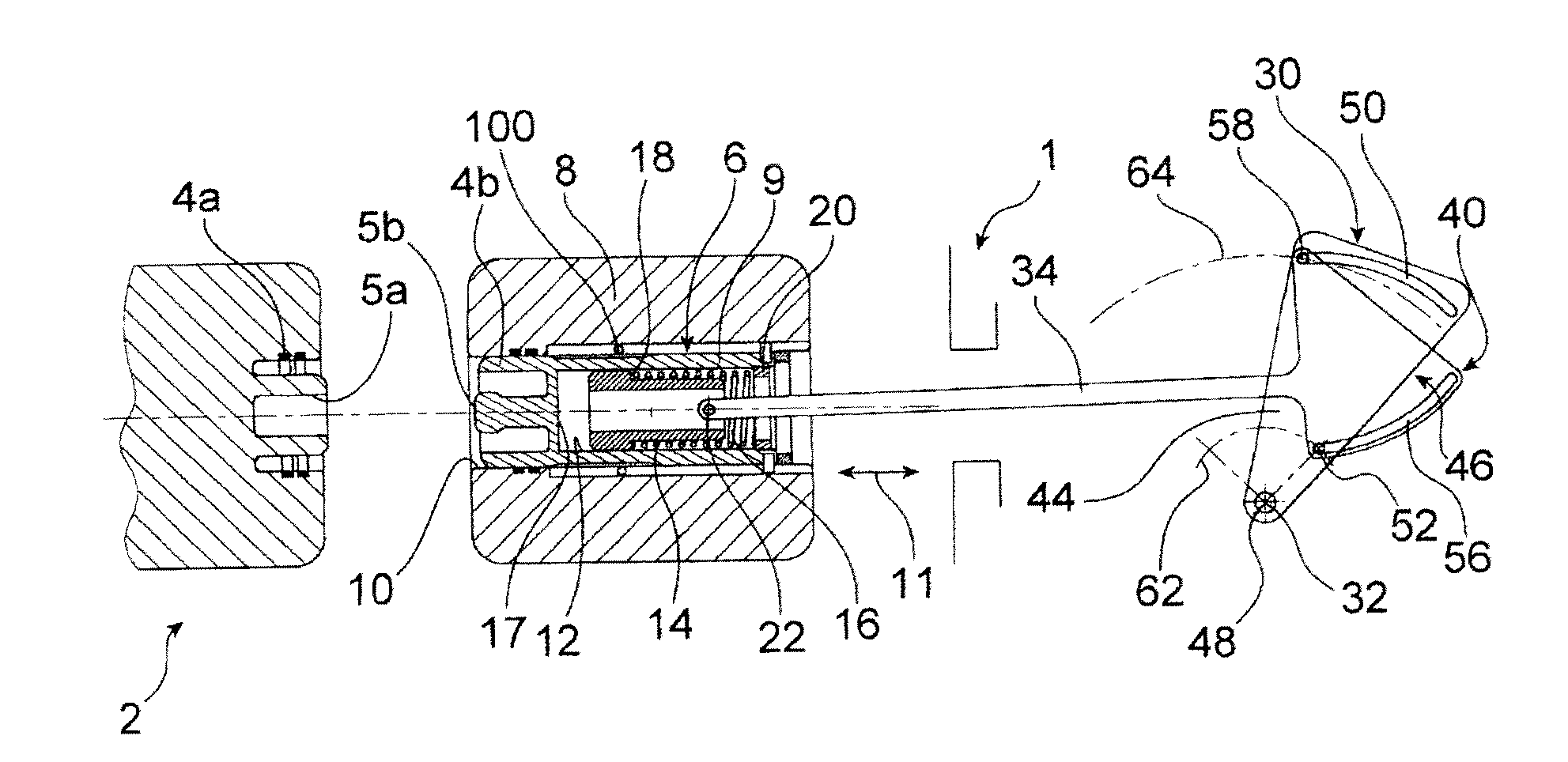
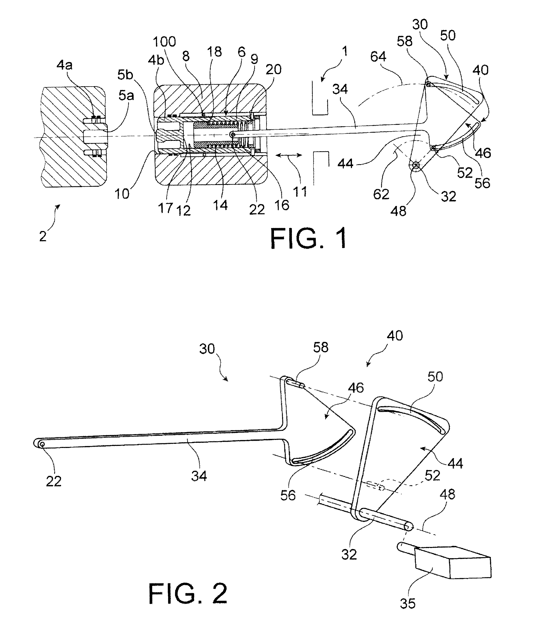
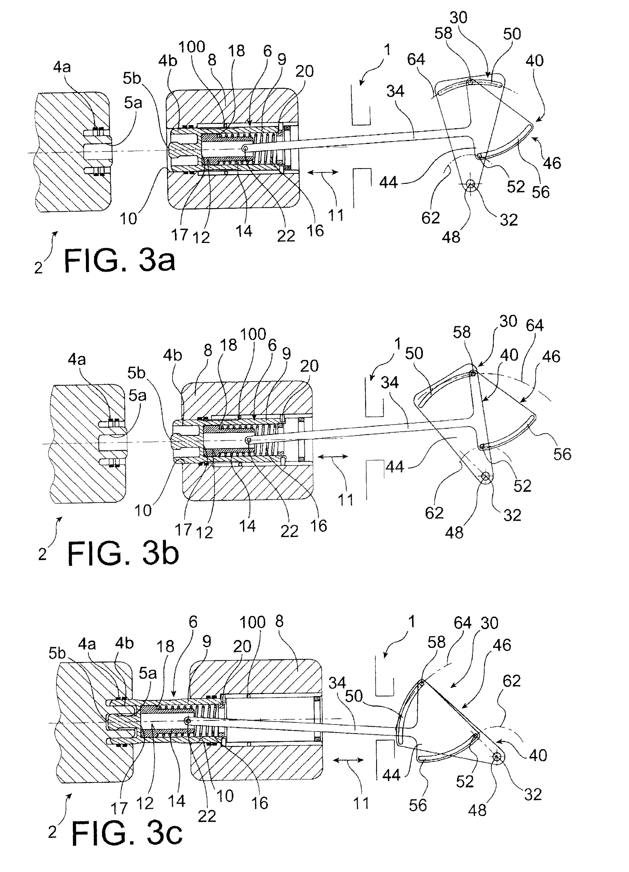
[0048]Firstly, FIGS. 1 and 2, show a portion of a disconnector in a preferred embodiment of the invention, said disconnector possibly being a grounding switch, preferably a high-voltage grounding switch.

[0049]The disconnector 1 comprises an arc-control chamber 2 shown only in part, enclosed in an enclosure containing an insulating gas such as SF6 or any other gaseous mixture known to be appropriate. The chamber 2 encloses a stationary main contact 4a, as well as a stationary arcing contact 5a, situated radially towards the inside relative to the main contact 4a. It also encloses an electrically conductive unit 6, that is electrically connected to a stationary body 8 in which it is movable in translation, along a movement axis represented by the double-headed arrow 11. This unit 6 presents an end fitted with a movable main contact 4b, and with a movable arcing contact 5b, for co-operating with the above-mentioned contacts 4a, 5a.

[0050]The unit 6 takes on the overall shape of a cylin...


PUM


Abstract

A disconnector (1) including a movable conductive unit (6) comprising a main electrically conductive body (9) has a main contact (4b) as well as an arcing contact (5b). According to the invention, the unit (6) further comprises a secondary body (14) mounted to move in sliding relatively to the main body (9) along a movement direction (11) of the unit (6), the secondary body (14) being designed to be connected to a connection point (22) of a drive device of the unit (6), the unit further comprising resilient return means (16) interposed between the bodies (9, 14), the switchgear being designed so that during an opening operation the resilient return means (16) can firstly store energy as a result of the secondary body (14) moving relative to the main body (9), and can then release the stored energy in order to cause the main body (9) to accelerate.

Description

TECHNICAL FIELD[0001]The present invention relates to the field of switchgear, in particular of the disconnector or grounding switch type, preferably high-voltage switchgear.[0002]More precisely, the invention relates to an electrically conductive unit of the switchgear, said unit being conventionally fitted with a main contact and with an arcing contact.PRIOR ART[0003]Conventionally, and in manner known to the person skilled in the art, the electrically conductive unit of switchgear of the disconnector or grounding switch type is moved in translation at a constant speed during each opening operation and during each closing operation.[0004]During those repeatedly-performed operations, the conductive unit, which generally takes the form of a cylinder fitted with a main contact and with an arcing contact, is subjected to mechanical and electrical stresses that gradually cause it to deteriorate. That phenomenon is also observed on the other main contact and on the other arcing contact ...

Claims


Application Information

Patent Timeline
IPC IPC(8): H01H33/42H01H33/46H01H33/36
CPCH01H33/42H01H2235/01H01H33/46H01H33/36H01H1/385H01H3/3052H01H3/46H01H31/32H01H33/12H01H33/40
Inventor BLANCHET, GUILHEMRAT-PATRON, LAURENT
Owner ALSTOM TECH LTD
Why Eureka
Try Eureka