Machining machine and method for operating a machining machine

a technology of machining machine and machining disk, which is applied in the direction of grinding machine components, lapping machines, manufacturing tools, etc., can solve the problems of affecting the result of machining, deviation in the geometry of the gap, and change in the working gap between the working disk, so as to achieve significant shortened setup procedures

Active Publication Date: 2017-08-10
PETER WOLTERS GMBH
View PDF5 Cites 3 Cited by
  • Summary
  • Abstract
  • Description
  • Claims
  • Application Information

AI Technical Summary

Benefits of technology

[0033]Given the unavoidable production and installation tolerances, working disks must be set up before they are operated for the first time, in particular in double-side machining machines. This is presently accomplished by an involved lapping process in which the working disks are machined to remove material over a long time until they possess the desired shape for subsequent operation. Because the bottom working disk is locally deformed in the aforementioned method...

Problems solved by technology

With machining machines of the kind at issue here, a change in the working gap arises between the working disks due to the process heat which arises during machining.
In particular, a heat-related deformation of the working disks occurs and he...

Method used


Image

  • Machining machine and method for operating a machining machine
  • Machining machine and method for operating a machining machine
  • Machining machine and method for operating a machining machine

Examples


Embodiment Construction

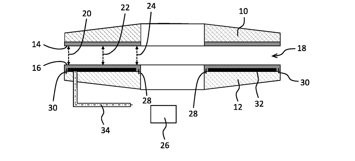
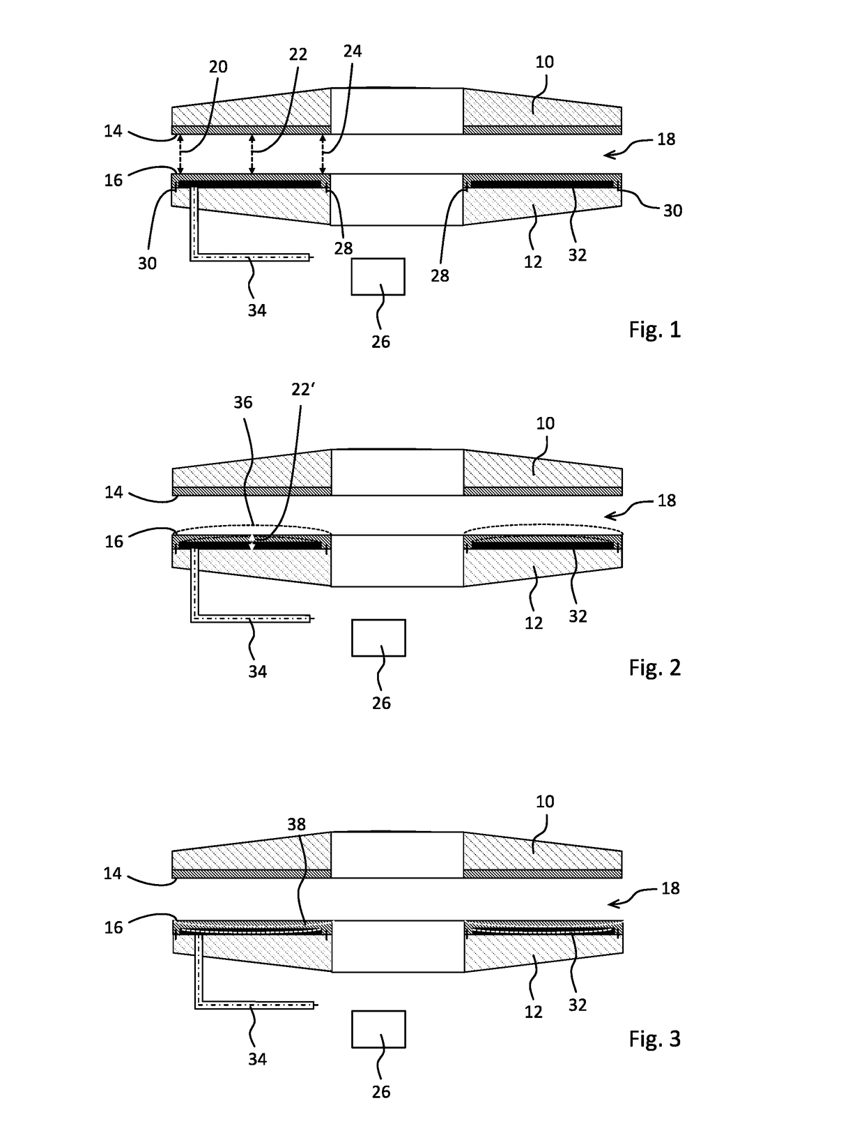
[0043]The double-side machining machine depicted merely as an example in FIGS. 1 to 3 has a top support disk 10 and a bottom support disk 12 that is annular. A top working disk 14 is fastened to the top support disk 10, and a bottom working disk 16 is fastened to the bottom support disk 12. Both the top working disk 14 and the bottom working disk 16 may be annular. Between the annular working disks 14, 16, a working gap 18 is formed in which flat workpieces such as wafers are machined on both sides during operation. The working gap 18 may be annular. The double-side machining machine can for example be a polishing machine, lapping machine, or a grinding machine.

[0044]The top support disk 10, with the top working disk 14, and / or the bottom support disk 12 with it the bottom working disk 16, can be rotatably driven relative to each other by a suitable drive apparatus comprising for example a top drive shaft (not shown), and / or a bottom drive shaft (not shown), as well as at least one ...


PUM

PropertyMeasurementUnit
Temperatureaaaaaaaaaa
Thicknessaaaaaaaaaa
Pressureaaaaaaaaaa

Abstract

A machining machine includes an annular bottom working disk and a top counter bearing element. The bottom working disk and top counter bearing element are driven to rotate relative to each other. A working gap is defined between the bottom working disk and the top counter bearing to machine flat work pieces on at least one side. A means for generating a local deformation of the bottom working disk are also provided.

Description

CROSS REFERENCE TO RELATED APPLICATION[0001]This application is based upon and claims priority to, under relevant sections of 35 U.S.C. §119, German Patent Application No. 10 2016 102 223.3, filed Feb. 9, 2016, the entire contents of which are hereby incorporated by reference.BACKGROUND[0002]The invention relates to a double-side or one-side machining machine with a preferably annular bottom working disk and a top counter bearing element, wherein the bottom working disk and top counter bearing element can be driven to rotate relative to each other Between the bottom working disk and top counter bearing element is a working gap to machine flat workpieces on two sides or one side. The invention also relates to a method for operating such a double-side or one-side machining machine, and a method for setting up at least one bottom working disk in a double-side or one-sided machining machine.[0003]For example, flat workpieces such as wafers are simultaneously machined on both sides in do...

Claims


Application Information

Patent Timeline
IPC IPC(8): B24B49/08B24B49/14B24B7/00
CPCB24B49/08B24B49/14B24B7/00B24B1/00B24B7/17B24B49/03B24B37/015B24B37/08B24B37/10B24B7/228H01L21/304
Inventor BOLLER, HANS-PETER
Owner PETER WOLTERS GMBH
Why Eureka
Try Eureka