Application circuit and control method thereof

a technology of application circuit and control method, which is applied in the field of circuits, can solve the problems of insufficient input current to provide the holding current required for turning on the triac itself, high wattage, and consuming more power during use, and achieves the effects of improving the control of power consumption, and improving the control of holding curren

Inactive Publication Date: 2014-11-27
LEXTAR ELECTRONICS CORP
View PDF6 Cites 2 Cited by
  • Summary
  • Abstract
  • Description
  • Claims
  • Application Information

AI Technical Summary

Benefits of technology

[0028]In view of the foregoing, the technical solutions of the present disclosure result in significant advantageous and beneficial effects, compared with existing techniques. The implementation of the above-mentioned technical solutions achieves substantial technical improvements and provides utility that is widely applicable in the industry. Specifically, technical advantages generally attained, by embodiments of the present invention, include:
[0029]1. The application circuit supports TRAIC for use in light-emitting diode drivers with low power consumption, such that the turn-on angle of the LED light bulb is comparable to that of the conventional bulb;
[0030]2. It is feasible to increase the control of holding current at low turn-on angle, that is, it can turn on the LED light source at the low turn-on angle;
[0031]3. When the inputted holding current is sufficient to maintain the ON status of the TRAIC, the application circuit may exclude the dynamic load, thereby reducing the energy consumption at the higher turn-on angle; and
[0032]4. Given the discrepancies in the quality of TRAICs from various brands, the application circuit may increase the adaptability of unit under test.

Problems solved by technology

Halogen light bulbs are loads that require high wattage, and consume more power during usage.
Nonetheless, LEDs are not transistor-type loads, and the power consumption thereof is about 9.3 W, which is much lesser than the conventional light sources, and hence, the input current is insufficient to provide the holding current required for turning on the TRIAC itself.
1. Due to the low power consumption of the LED light source, the TRIAC control can only turn on the LED light source at a higher turn-on angle;
2. At the lower turn-on angle, the fidelity of the TRIAC wave form will decrease, thereby resulting in the flickering of the LED light source, which may make the users feel uncomfortable;
3. The discrepancies in the quality of commercial TRIACs from various brands tend to cause the problems associated with matching of the unit under test.
In view of the foregoing, there exist problems and disadvantages in the existing products that await further improvement.
However, those skilled in the art sought vainly for a solution.

Method used


Image

  • Application circuit and control method thereof
  • Application circuit and control method thereof
  • Application circuit and control method thereof

Examples


Embodiment Construction

[0037]In the following detailed description, for purposes of explanation, numerous specific details are set forth in order to attain a thorough understanding of the disclosed embodiments. In accordance with common practice, the various described features / elements are not drawn to scale but instead are drawn to best illustrate specific features / elements relevant to the present invention. Also, like reference numerals and designations in the various drawings are used to indicate like elements / parts. Moreover, well-known structures and devices are schematically shown in order to simplify the drawing and to avoid unnecessary limitation to the claimed invention.

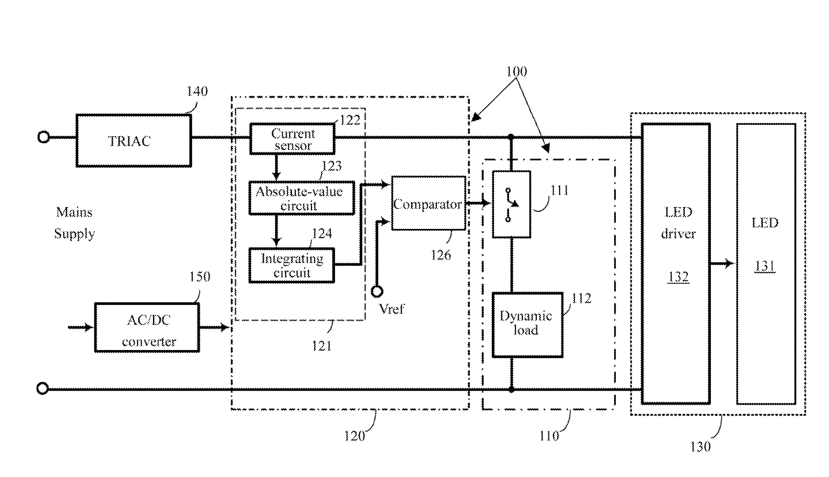
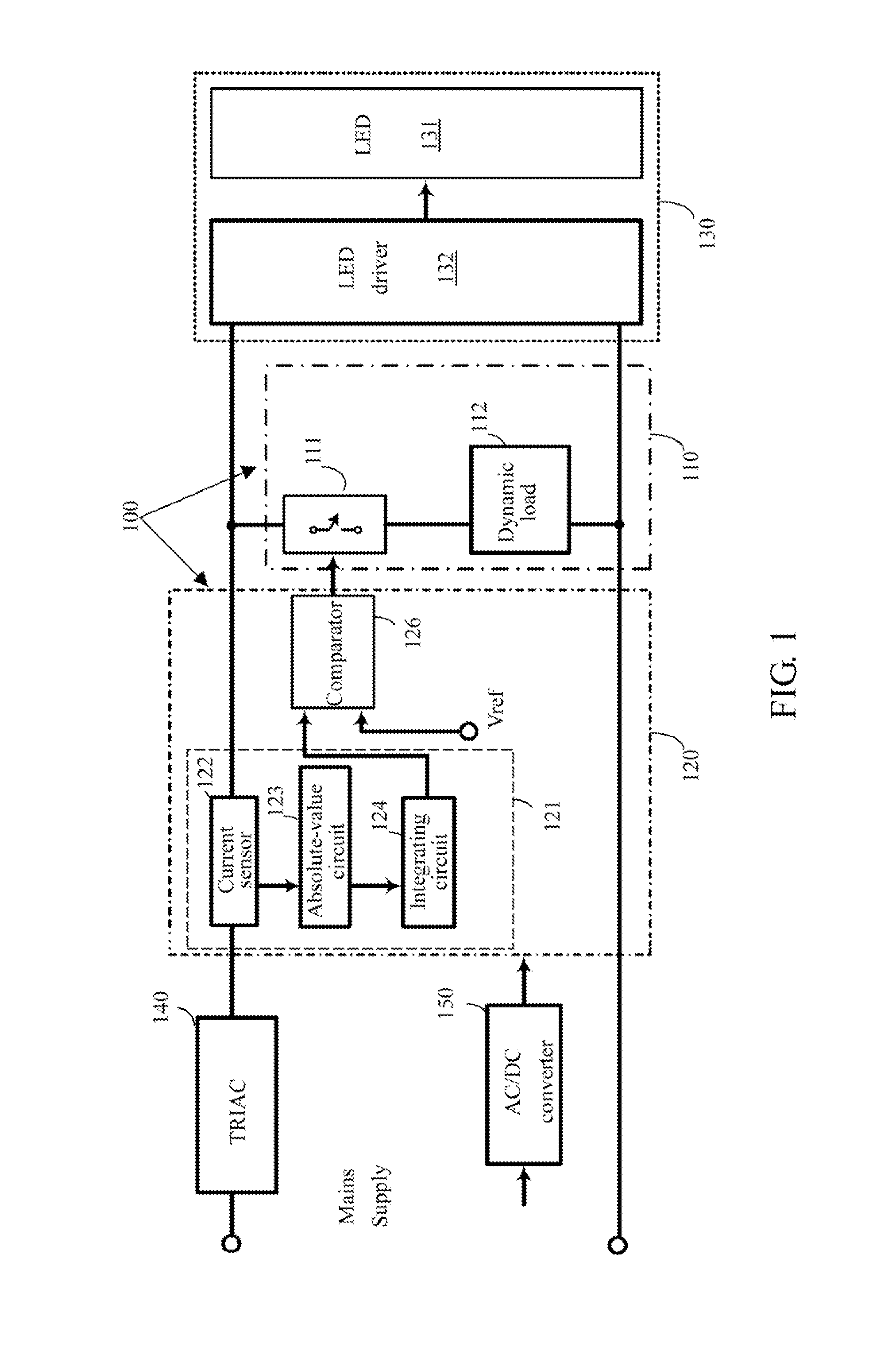
[0038]FIG. 1 is a block diagram illustrating an application circuit 100 according to embodiments of the present disclosure. As illustrated in FIG. 1, the application circuit 100 comprises a dynamic load circuit 110 and a control circuit 120. In structure, the dynamic load circuit 110 is electrically connected to the light source 1...


PUM


Abstract

An application circuit includes a dynamic load circuit and a control circuit. The dynamic load circuit is electrically connected to a light source. The control circuit is electrically connected to the dynamic load circuit and a TRIAC. The control circuit controls the load status of the dynamic load circuit based on output current from the TRIAC, so as to turn on the light source.

Description

RELATED APPLICATIONS[0001]This application claims priority to Taiwan Patent Application No. 102118531, filed May 24, 2013, the entirety of which is herein incorporated by reference.BACKGROUND[0002]1. Technical Field[0003]The present disclosure relates to a circuit; more particularly, an application circuit and a control method thereof.[0004]2. Description of Related Art[0005]Conventional dimmers adopt the structure of triode for alternating current (TRIAC); since incandescent light sources are resistor-type loads, they are primarily used in adjusting the brightness of the incandescent light sources. When adjusting the angle of the external knob of the dimmer, the resistance value of the variable resistor within the dimmer will also change accordingly, thereby accomplishing the control of the brightness / darkness of the outputted light.[0006]For example, the incandescent light sources may be halogen light bulbs which is a resistor-type load and connected with a commercially-available ...

Claims


Application Information

Patent Timeline
Patent Type & Authority Applications(United States)
IPC IPC(8): H05B33/08H05B44/00
CPCH05B33/0842H05B33/0815H05B45/3575H05B45/31
Inventor CHEN, CHUN-KUANGCHEN, PO-SHEN
Owner LEXTAR ELECTRONICS CORP
Why Eureka
Try Eureka