Electrode pattern of touch panel and method of manufacturing the same

Inactive Publication Date: 2014-11-27
LG INNOTEK CO LTD
View PDF10 Cites 5 Cited by
  • Summary
  • Abstract
  • Description
  • Claims
  • Application Information

AI Technical Summary

Benefits of technology

[0019]According to the present invention, as the conductive patterns (Rx, Tx) are all formed on one substrate, the electrode pattern can be efficiently formed compared to the conventional art, so that the touc

Problems solved by technology

However, according to the conventional art, to form the second conductive pattern 130, the conductive transparent material coating layer 132 is formed by a

Method used


Image

  • Electrode pattern of touch panel and method of manufacturing the same
  • Electrode pattern of touch panel and method of manufacturing the same
  • Electrode pattern of touch panel and method of manufacturing the same

Examples


Example

[0028]Hereinafter, preferred embodiments of the present invention will be described in detail with reference to the accompanying drawings. In the following description, it is to be noted that, when the functions of conventional elements and the detailed description of elements related with the present invention may make the gist of the present invention unclear, a detailed description of those elements will be omitted. Further, it should be understood that the shape and size of the elements shown in the drawings may be exaggeratedly drawn to provide an easily understood description of the structure of the present invention rather than reflecting the actual sizes of the corresponding elements.

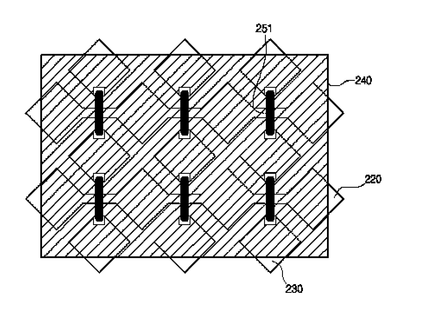
[0029]An electrode pattern of a touch panel according to one exemplary embodiment of the present invention will be explained with reference to FIG. 4 through FIG. 6.

[0030]FIG. 4 and FIG. 5 are views illustrating an electrode pattern of a touch panel according to one exemplary embodiment of the p...


PUM


Abstract

Provided is an electrode panel of a touch panel and a method of manufacturing the same, the method, including: forming a plurality of electrode pattern cells on a substrate to be space apart from each other; forming an insulating layer on the electrode pattern cells; forming a hole on the insulating layer; and forming a bridge electrode and fills the hole with a conductive material.

Description

TECHNICAL FIELD[0001]The present invention relates to an electrode pattern of a touch panel and a method of manufacturing the same, more specifically, to an electrode pattern of a touch panel and a method of manufacturing the same, which can be efficiently produced with a low cost.BACKGROUND ART[0002]A touch panel has been widely used in electrical apparatuses such as personal digital assistants, notebook computers, OA apparatuses or car navigation systems in order to provide an input means (i.e. pointing device) into their display devices. A resistive-based touch panel, an electronic inductive type touch panel, an optical touch panel, and a capacitive type touch panel have been known as representative touch panels.[0003]In generally, a capacitive type touch panel is divided into an analogue type touch panel and a digital type touch panel.[0004]In the analogue type touch panel, a sensor electrode is an electrode in a sheet shape, so no pattern is required in a sensing operation area...

Claims


Application Information

Patent Timeline
IPC IPC(8): G06F3/044
CPCG06F2203/04111G06F3/044G06F2203/04103G06F3/0445G06F3/0446G06F3/0448H01B5/14H01B13/00
Inventor JANG, JAE JOONHONG, HYUK JINJO, JI WON
Owner LG INNOTEK CO LTD
Why Eureka
Try Eureka