
System and Method for Simulation of Gas Desorption in a Reservoir Using a Multi-Porosity Approach

a gas desorption and multi-porosity technology, applied in the field of system and method for simulation of gas desorption in a reservoir using a multi-porosity approach, can solve the problems of different fluid retention and transport properties of vug pore system, and traditional dual-porosity reservoir modeling techniques cannot adequately predict mass transfer and fluid flow characteristics of shale reservoirs

Inactive Publication Date: 2014-11-27
LANDMARK GRAPHICS
View PDF2 Cites 2 Cited by
  • Summary
  • Abstract
  • Description
  • Claims
  • Application Information

AI Technical Summary

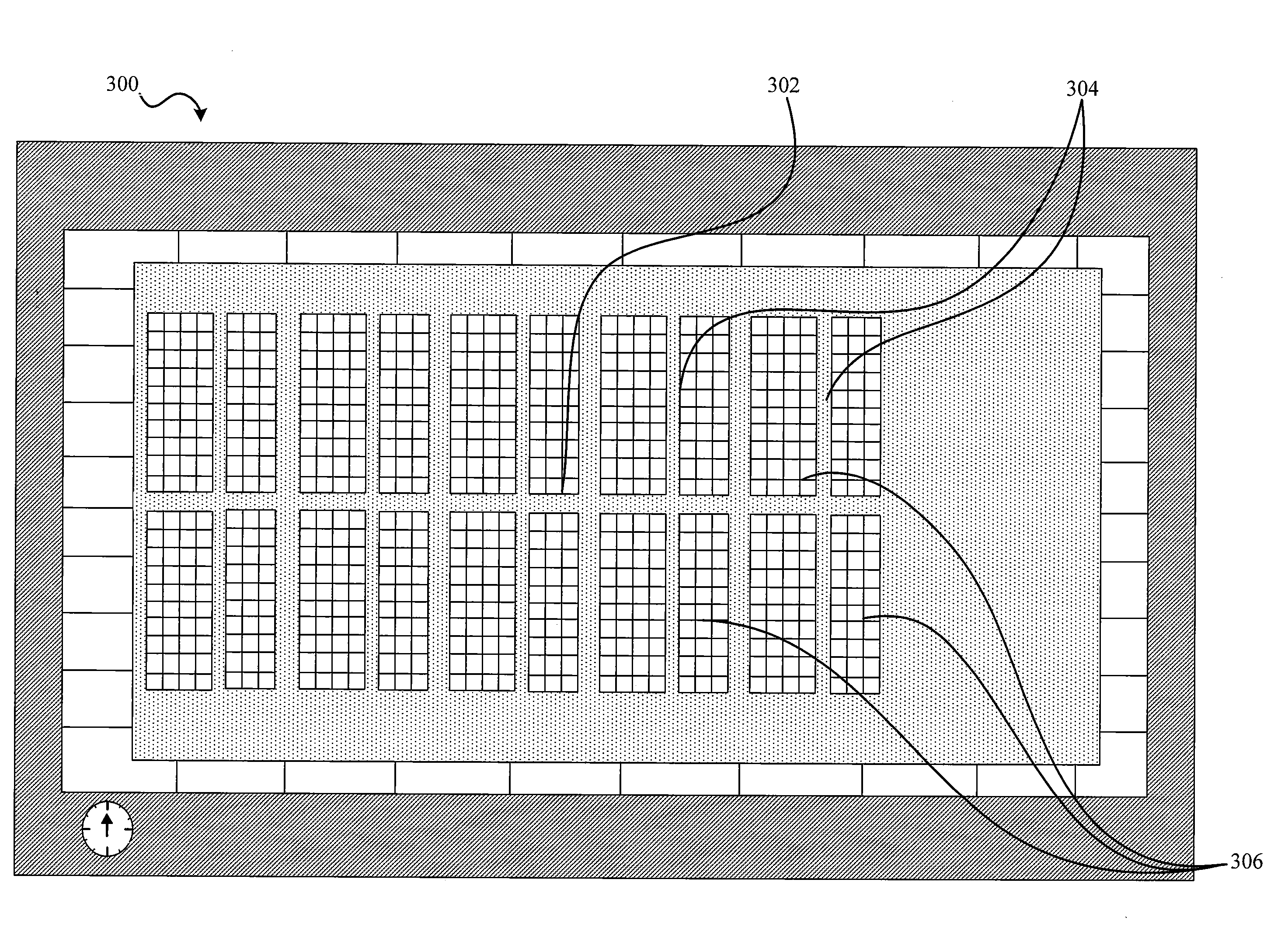
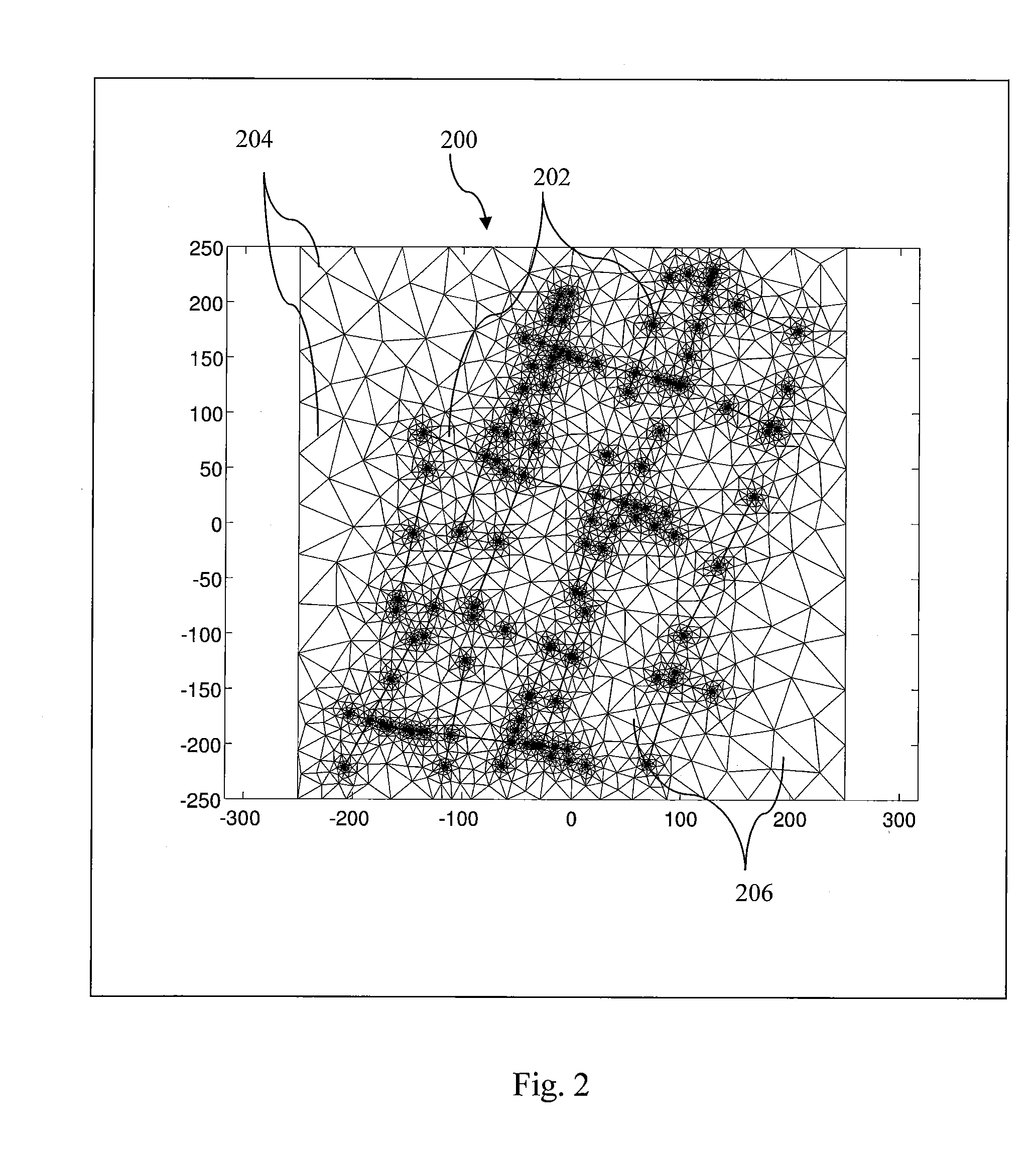
Benefits of technology

The patent text describes a new method and system for simulating the behavior of gas in shale gas reservoirs. The method and system incorporate a unique way of handling gas desorption by rigorously simulating the flow mechanism that occurs therein. This is important because traditional methods have only used the matrix porosity system and the induced fracture porosity systems in reservoir modeling, but the new method and system incorporate natural fracture porosity systems and vug porosity systems as well. This allows for a more accurate prediction of mass transfer and fluid flow characteristics in shale gas reservoirs, which are important for oil and gas producers in determining how to develop new fields and make informed investment decisions.

Problems solved by technology

Fractured reservoirs present special challenges for simulation because of the multiple porosity systems or structures that may be present in these types of reservoirs.
Because of their separate physical and mechanical characteristics, the fluid retention and transport properties of vug pore systems are different from those of both the matrix and fracture systems, and have not heretofore been adequately addressed with analysis utilizing only matrix porosity systems and induced porosity systems.
In other words, because of the geologic complexities of shale reservoirs, traditional dual porosity reservoir modeling techniques do not adequately predict mass transfer and fluid flow characteristics of shale reservoirs.

Method used


Image

  • System and Method for Simulation of Gas Desorption in a Reservoir Using a Multi-Porosity Approach
  • System and Method for Simulation of Gas Desorption in a Reservoir Using a Multi-Porosity Approach
  • System and Method for Simulation of Gas Desorption in a Reservoir Using a Multi-Porosity Approach

Examples


Embodiment Construction

[0011]To overcome the above-noted and other limitations of the current approaches, one or more embodiments described herein comprise a reservoir simulator including a unique manner of handling gas desorption in shale gas reservoir simulations by rigorously simulating the flow mechanism that occurs therein.

[0012]It has been found that the mechanism for desorption of gas in a shale gas reservoir is based on the existence of four separate porosity systems, each of which is incorporated in the method and system of the invention. In the method and system of the invention, each of these four porosity systems is separately characterized and incorporated into the model. The four porosity systems are the matrix porosity system, the induced fracture porosity systems, the natural fracture porosity system and the vug porosity system. As explained above, heretofore, only the matrix porosity system and the induced fracture porosity systems have been used in reservoir modeling in the past. The met...


PUM


Abstract

A hydrocarbon shale reservoir simulation system and method represented by a model having at least four different types of porosity nodes is described. The method includes the computer-implemented steps of characterizing porosity nodes within the model as one of natural fracture pore systems, matrix pore systems, induced fracture pore systems or vug pore systems. Following characterization, transfer terms between nodes are identified. Transfer terms may include transfer terms between vug nodes, matrix nodes, natural fracture nodes and induced fracture nodes. Once transfer terms have been assigned, the linear system for the model can be solved utilizing a linear solver. The method further includes the steps of utilizing the characterized pore nodes to define one or more subgrids that represent a zone within the reservoir, wherein the zone includes at least one node of each porosity type; and wherein the linear solver is applied by subgrid or associated sub-grids.

Description

CROSS-REFERENCE TO RELATED APPLICATION(S)[0001]This application is a continuation-in-part, and claims priority to, PCT Application No. PCT / US2011 / 44178, filed Jul. 15, 2011, assigned to the assignee of the present application, and hereby incorporated by reference in its entirety.BACKGROUND[0002]Reservoir simulation is an area of reservoir engineering that employs computer models to predict the transport of fluids, such as petroleum, water, and gas, within a reservoir. Reservoir simulators are used by petroleum producers in determining how best to develop new fields, as well as in generating production forecasts on which investment decisions are based in connection with developed fields.[0003]Fractured reservoirs present special challenges for simulation because of the multiple porosity systems or structures that may be present in these types of reservoirs. Fractured reservoirs are traditionally modeled by representing the porous media using two co-exiting pore systems or structures ...

Claims


Application Information

Patent Timeline
Patent Type & Authority Applications(United States)
IPC IPC(8): E21B43/00
CPCE21B43/00E21B49/00G01V11/00E21B43/16E21B2200/20G01N2203/006G01N2203/0067G01V2210/66G01V20/00
Inventor KILLOUGH, JOHN EDWIN
Owner LANDMARK GRAPHICS
Learn More