Fuel vapor processing apparatus

a technology of fuel vapor and processing apparatus, which is applied in mechanical apparatus, machine/engine, separation processes, etc., can solve the problems of fuel components insufficient desorption and fuel component degradation in the next adsorption layer

Active Publication Date: 2014-12-04
AISAN IND CO LTD
View PDF0 Cites 23 Cited by
  • Summary
  • Abstract
  • Description
  • Claims
  • Application Information

AI Technical Summary

Benefits of technology

[0009]In one form, the invention is directed to a fuel vapor processing apparatus including: a passage for a fluid to flow through formed inside the apparatus; a tank port and a purge port formed on one end side of the passage; an atmospheric air port formed on other end side of the passage; and four or more adsorption layers provided in the passage. The four or more adsorption layers are filled with an adsorbing material capable of adsorbing fuel components. The fuel vapor processing apparatus further includes a main adsorption layer and a region provided on t...

Problems solved by technology

This causes degradation of the desorption performance in the next adsorption layer and insufficient desorption of the fuel components.
As a resul...

Method used


Image

  • Fuel vapor processing apparatus
  • Fuel vapor processing apparatus
  • Fuel vapor processing apparatus

Examples


embodiment 1

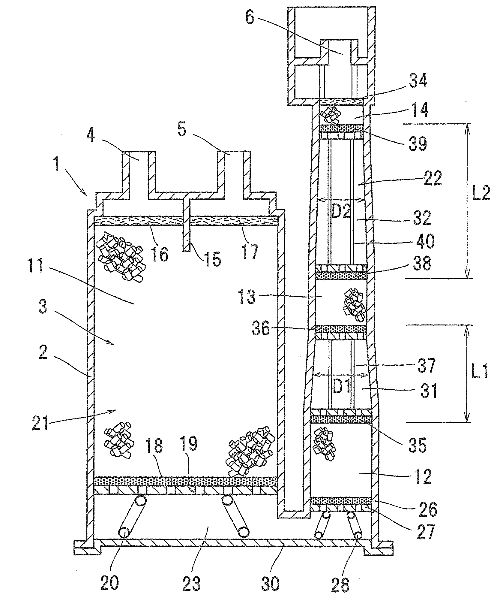
[0021]FIG. 1 shows Embodiment 1 of the present invention.

[0022]As shown in FIG. 1, a fuel vapor processing apparatus 1 of the present invention includes: a casing 2; a passage 3 for a fluid to flow through formed inside the casing 2; a tank port 4 and a purge port 5 formed in an end part on one end side of the passage 3 in the casing 2; and an atmospheric air port 6 formed in an end part on the other end side.

[0023]Four adsorption layers, namely, a first adsorption layer 11, a second adsorption layer 12, a third adsorption layer 13, and a fourth adsorption layer 14, each filled with an adsorbing material capable of adsorbing vaporized fuel components are arranged in series in the passage 3. In this embodiment, activated carbon is used as the adsorbing material.

[0024]As shown in FIG. 1, a first region 21 communicating with the tank port 4 and the purge port 5, and a second region 22 communicating with the atmospheric air port 6 are formed inside the casing 2, and the first region 21 ...

embodiment 2

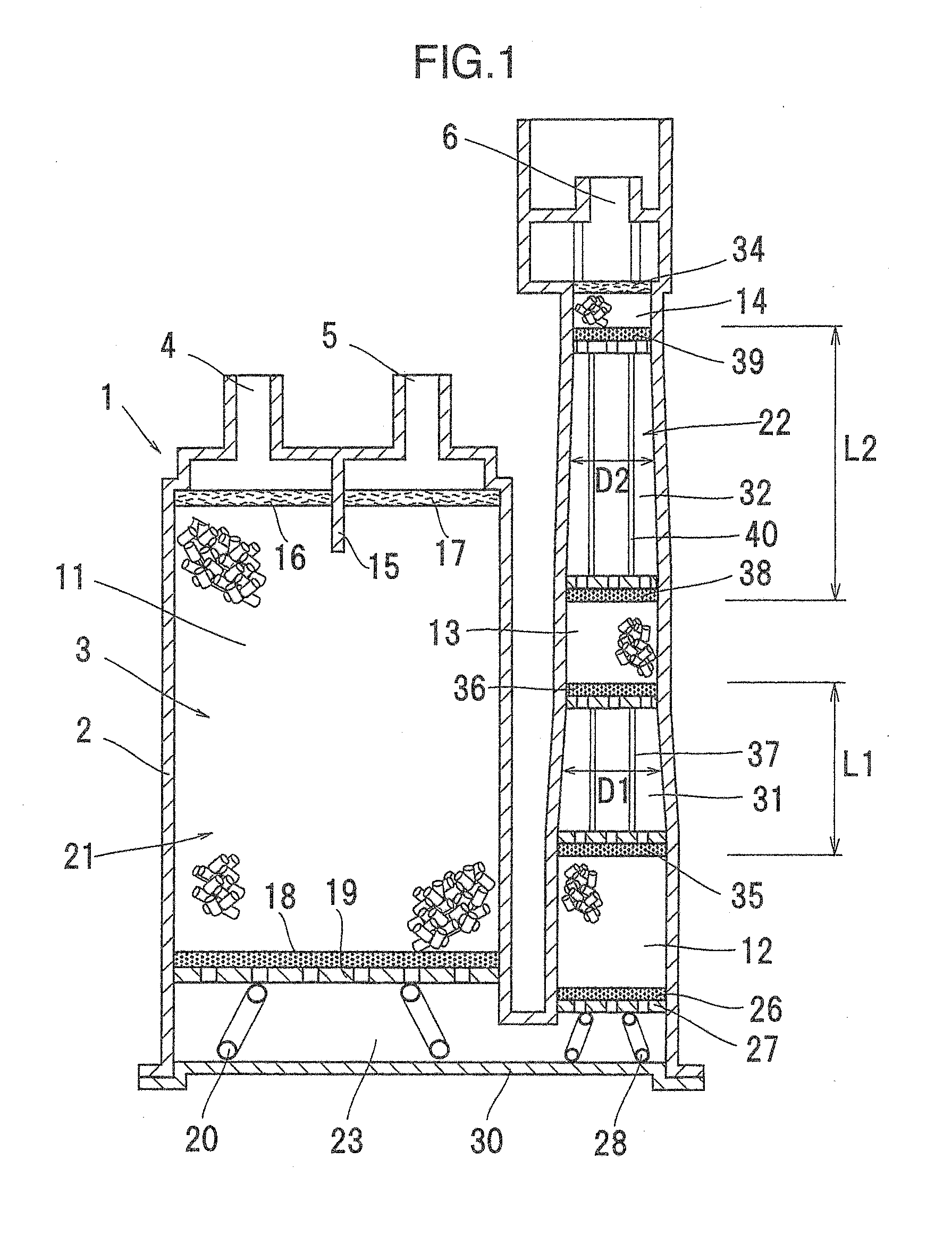
[0052]While the passage 3 of a U-shape with one turnaround in the space 23 is formed inside the casing 2 in Embodiment 1, as shown in FIG. 2, for example, a passage 41 may be formed in an N-shape with two turnarounds inside the casing 2.

[0053]The structure of the first region 21 of Embodiment 2 is similar to that of the first region 21 of Embodiment 1. In Embodiment 2, a second region 42 is formed in a U-shape with one turnaround in a space 43, and one end of the second region 42 communicates with the space 23, while the other end is provided with the atmospheric air port 6.

[0054]A second adsorption layer 12 and third adsorption layer 13 similar to those of Embodiment 1 are provided between the spaces 23 and 43 inside the second region 42, and the first separation part 31 is provided between the second adsorption layer 12 and the third adsorption layer 13. A fourth adsorption layer 14 similar to the fourth adsorption layer 14 of Embodiment 1 is provided on the atmospheric air port 6...

embodiment 3

[0059]Embodiment 3 differs in the shape of the passage from the passages 3 and 41 of Embodiments 1 and 2; as shown in FIG. 3, for example, a passage 51 may be formed in a W-shape with three turnarounds inside the casing 2.

[0060]The structure of the first region 21 of Embodiment 3 is similar to that of the first region 21 of Embodiment 1. In Embodiment 3, a second region 52 is formed in an N-shape with two turnarounds in spaces 53 and 54, and one end of the second region 52 communicates with the space 23, while the other end is provided with the atmospheric air port 6.

[0061]A second adsorption layer 12 and third adsorption layer 13 similar to those of Embodiment 1 are provided between the spaces 23 and 53 in the second region 52, and the first separation part 31 is provided between the second adsorption layer 12 and the third adsorption layer 13. A fourth adsorption layer 14 similar to that of Embodiment 1 is provided between the spaces 53 and 54. A second separation part 32 is provi...


PUM


Abstract

A fuel vapor processing apparatus including: a passage for fluid; a tank port and a purge port formed on one end side of the passage; an atmospheric air port formed on the other end side; and four or more adsorption layers filled with a fuel adsorbing material, wherein the main adsorption layer, and a region provided on the atmospheric air port side of the main adsorption layer are provided; the adsorption layers other than the main adsorption layer, and separation parts which separate the adjacent adsorption layers are provided in the region, and in the at least two separation parts inside the region, when the cross-sectional area of each of the at least two separation parts perpendicular to a flow direction of the passage is converted into a circular cross-sectional area, a distance between the adjacent adsorption layers is larger than the mean value of diameters of the each separation part.

Description

BACKGROUND OF THE INVENTION[0001]1. Field of the Invention[0002]The present invention relates to a fuel vapor processing apparatus.[0003]2. Background Art[0004]Conventionally, to prevent emission of fuel vapor to the atmosphere from a fuel tank of a car, etc., a fuel vapor processing apparatus (hereinafter also called a canister) which temporarily adsorbs fuel components present in fuel vapor is used.[0005]One of such canisters is known (JP-A-2007-146793) which includes: a casing formed with a tank port, a purge port, and an atmospheric air port; four adsorption layers filled with activated carbon and arranged in series inside the casing; and spaces, which are not filled with activated carbon, formed between the adjacent adsorption layers.[0006]In the canister, the temperature significantly falls during purge in an adsorption layer which is close to the atmospheric air port when fuel components are desorbed from the activated carbon filling the adsorption layer. In the canister of t...

Claims


Application Information

Patent Timeline
IPC IPC(8): F02M25/08
CPCF02M25/0854B01D53/0407B01D2259/4516F02M25/0872
Inventor MANI, TAKASHI
Owner AISAN IND CO LTD
Why Eureka
Try Eureka