Directional valve and method of operation

Active Publication Date: 2014-12-04
SPX FLOW INC
View PDF1 Cites 6 Cited by
  • Summary
  • Abstract
  • Description
  • Claims
  • Application Information

AI Technical Summary

Benefits of technology

The present invention provides an apparatus and method for dissipating the energy of high velocity hydraulic fluid without causing damage to valve components. Additionally, the invention facilitates the use of reduced amounts of energy to actuate hydraulic valves. The invention also includes a method for reducing erosion within the valve assembly by configuring the valve to restrict fluid flow when a conical valve portion is proximate to a valve seat and to open flow when the conical valve portion is not proximate to the valve seat.

Problems solved by technology

This high velocity fluid can create problems such as erosion within the hydraulic system.
This narrow gap while the valve is in the transition between being closed and open may be subject to wear and or erosion resulting from the energy dissipation of the hydraulic fluid.
This erosion may, in some instances, leads to valve failure and / or leakage.

Method used


Image

  • Directional valve and method of operation
  • Directional valve and method of operation
  • Directional valve and method of operation

Examples


Embodiment Construction

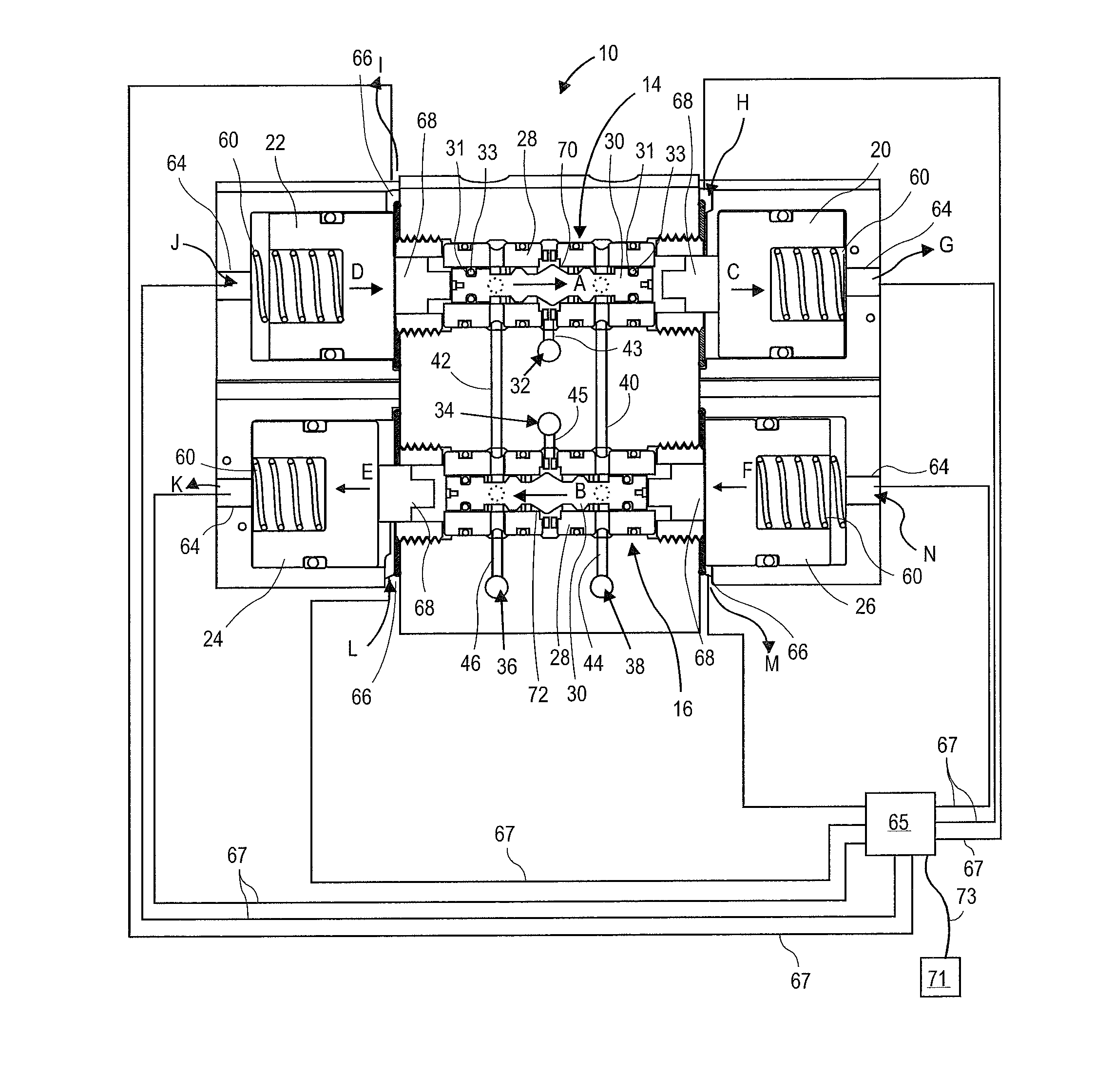
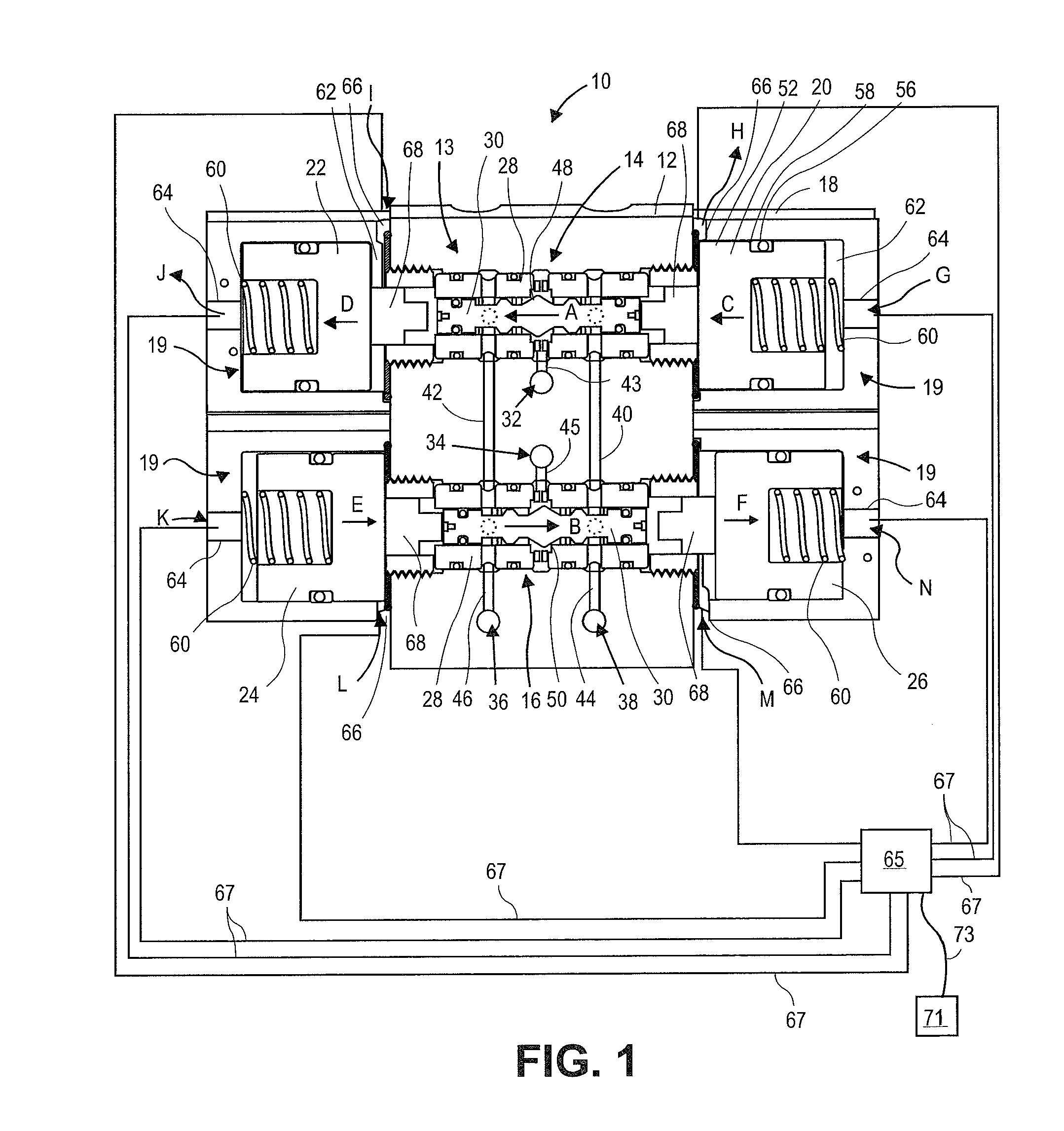
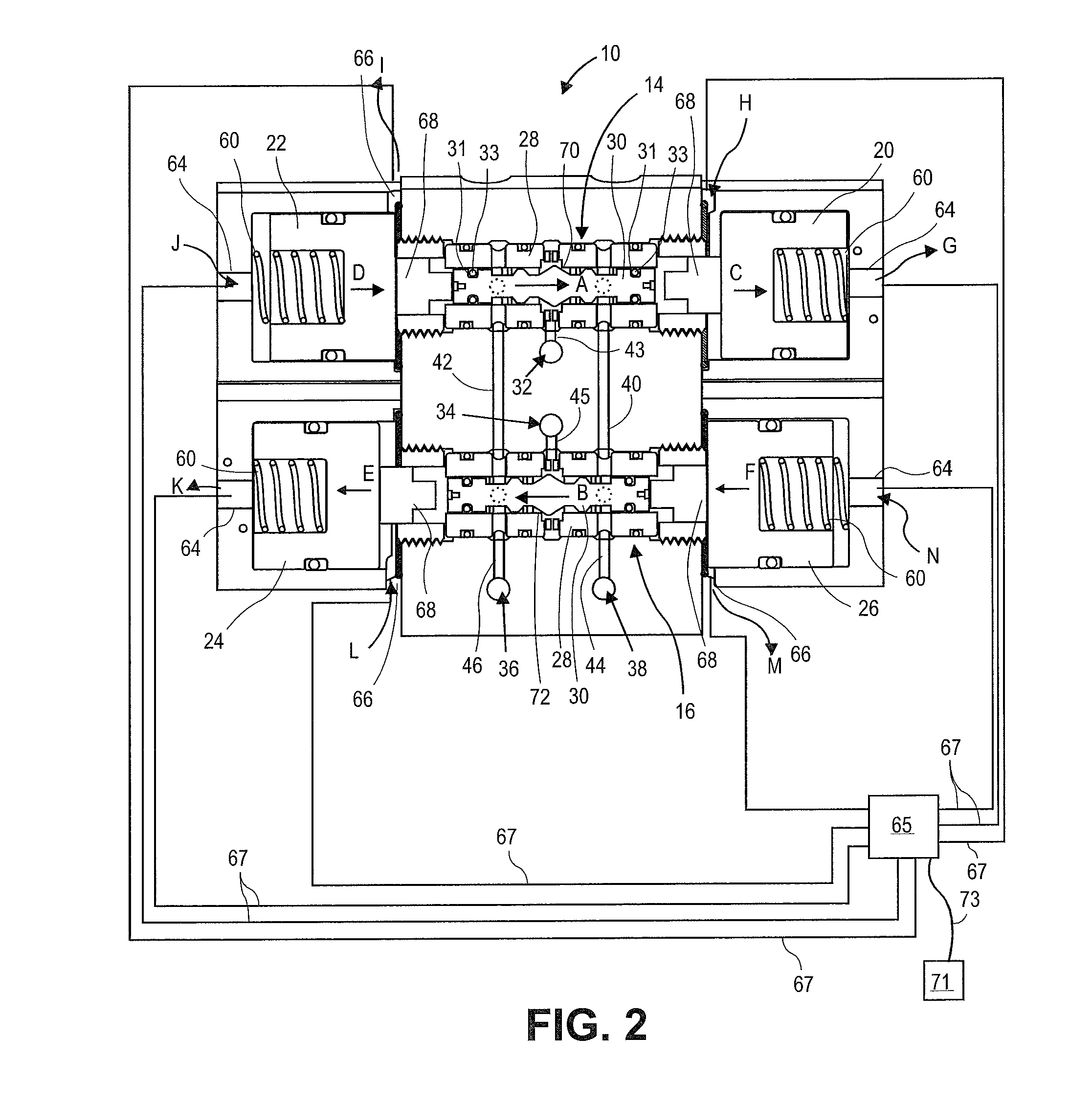
[0019]The invention will now be described with reference to the drawing figures, in which like reference numerals refer to like parts throughout. An embodiment in accordance with the present invention provides a system and method that includes at least one directional valve and multiple stage sealing methods. For example, a valve block may contain multiple valves. The valve block may be part of a hydraulic system. The various valves within the valve block may be selectively in fluid communication with each other.

[0020]Hydraulic fluid that flows through the valve block may, at certain times, be traveling at relatively high velocity. When various valves within the system close the high velocity fluid is suddenly stopped. The energy contained by the high velocity fluid may be dissipated using various means such as heat. However, when the valve is in a transitional state (i.e., between not fully seated and not fully opened) high velocity fluid may erode the valve or the valve seat. The ...


PUM


Abstract

A valve is provided. The valve may include: an axially movable spool having a conical valve portion and dissipating disk portion; a valve housing defining a valve cavity in which the spool resides; a first port in the valve housing; a second port in the valve housing; a land defined by the housing; a wide portion in the housing; and a valve seat defined, at least in part, by the valve housing configured to form a seal with the conical valve portion, wherein the land, the wide portion, the conical valve portion, and the valve seat are dimensioned to cause the disk portion and the land to be proximate to each other when the valve section is near the valve seat and the disk portion is proximate to the wide portion when the valve section is away from the valve seat.

Description

FIELD OF THE INVENTION[0001]This disclosure is directed to hydraulic valves. More particularly, it is directed to a double actuating spool valve and a system and method for actuating the valves.BACKGROUND OF THE INVENTION[0002]Hydraulic systems often use hydraulic valves in order to control the hydraulic system. One common type of valve is a spool poppet directional valve. Hydraulic systems may have hydraulic fluid being moved at high velocity. This high velocity fluid can create problems such as erosion within the hydraulic system. For example, high velocity fluid contains a lot of energy when a poppet valve is near or approaching its seat, the fluid is forced to slow down as it flows between the not yet seated poppet valve and its seat. This narrow gap while the valve is in the transition between being closed and open may be subject to wear and or erosion resulting from the energy dissipation of the hydraulic fluid. This erosion may, in some instances, leads to valve failure and / o...

Claims


Application Information

Patent Timeline
IPC IPC(8): F16K11/07
CPCF16K11/07F16K11/0708F16K11/044Y10T137/8663Y10T137/86879Y10T137/86887
Inventor LANDRUM, MICHAEL T.
Owner SPX FLOW INC
Why Eureka
Try Eureka