Absorption chiller

Active Publication Date: 2019-05-23
CHILLTECH
View PDF21 Cites 0 Cited by
  • Summary
  • Abstract
  • Description
  • Claims
  • Application Information

AI Technical Summary

Benefits of technology

The technical effects of this patent arrangement are that it improves the efficiency of an absorption chiller system by using waste heat from the system to heat up the working fluid before it re-enters the boiler, which reduces the amount of energy required. This arrangement utilizes two-stage heating of the working fluid and also utilizes heat that is generated while cooling the fluid during the process. This reduces energy usage by the absorption chiller and increases efficiency.

Problems solved by technology

However, the use of a heat source, typically an exhaust gas or gas powered heat source, to produce a cooling effect results in a lot of waste heat and results in a poor efficiency of the overall system when compared to other types of chillers.

Method used


Image

  • Absorption chiller
  • Absorption chiller
  • Absorption chiller

Examples


Embodiment Construction

)

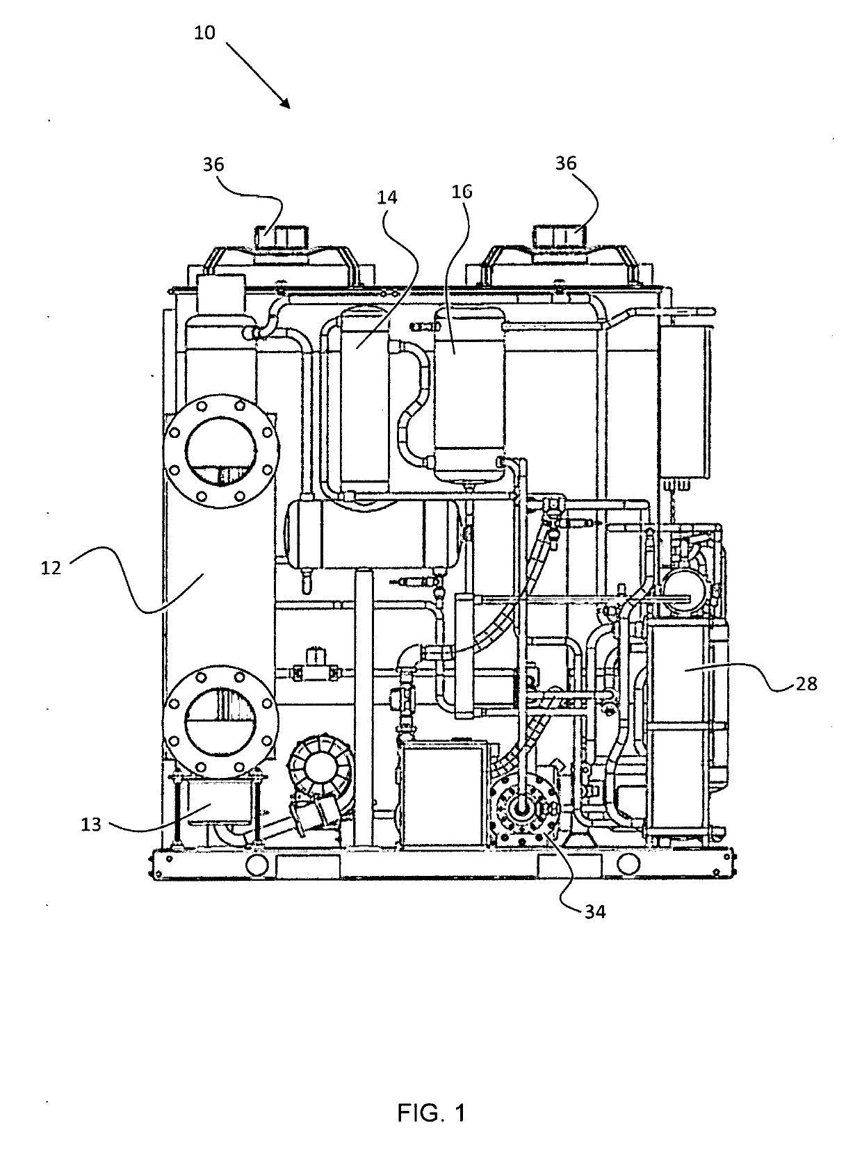
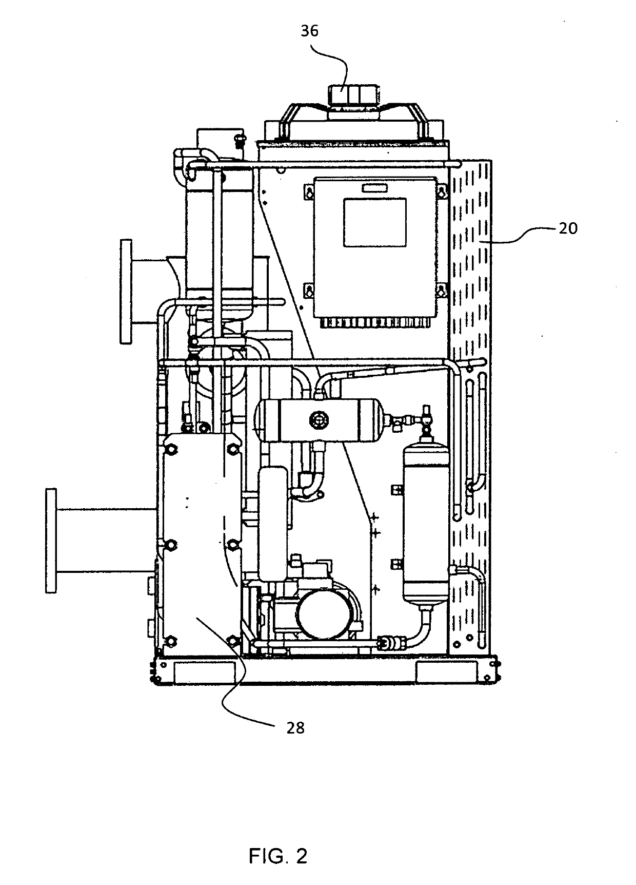
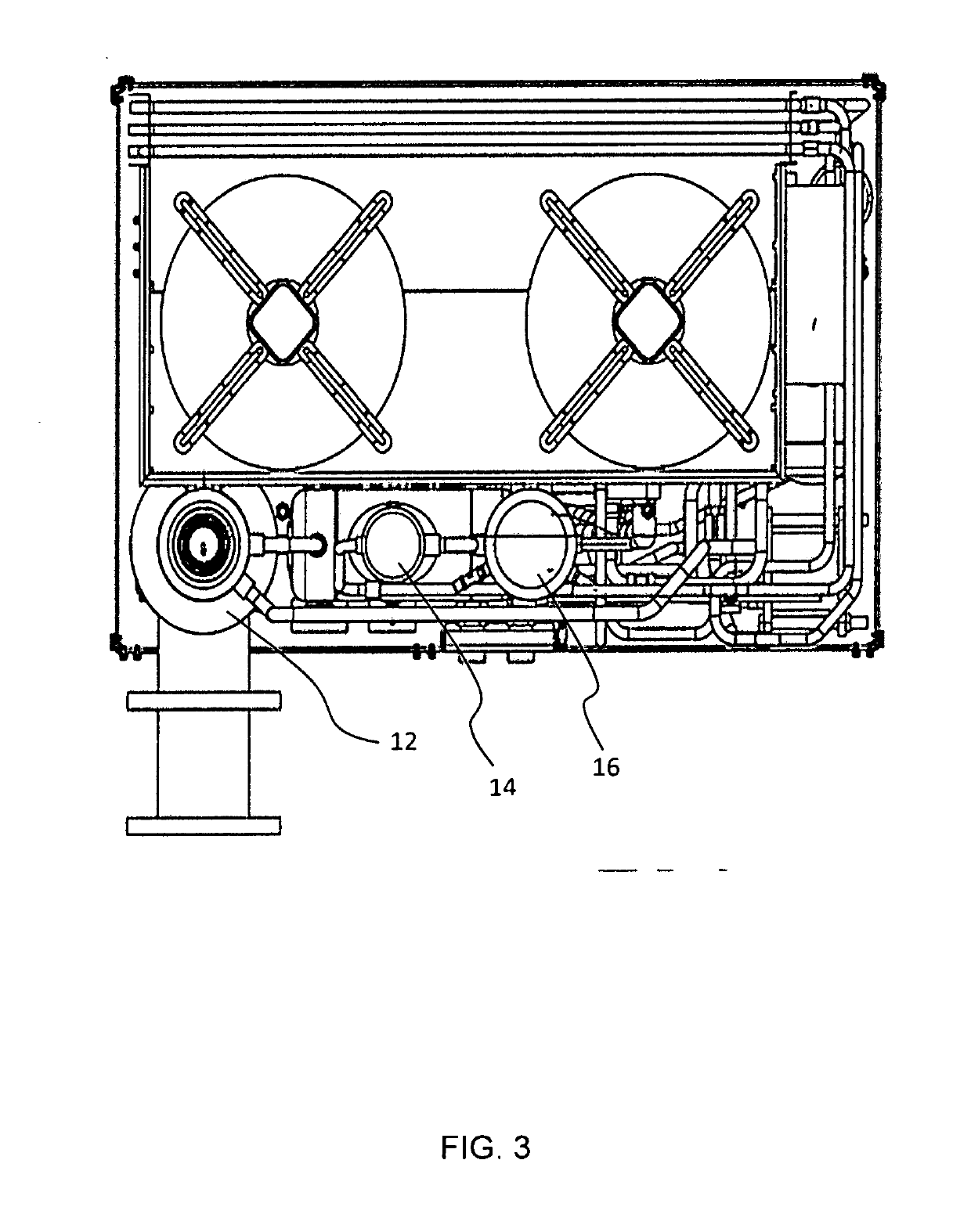
[0031]Referring to FIGS. 1 to 4, an absorption chiller is illustrated generally at 10. The absorption chiller 10 comprises a boiler 12 which includes a vessel (not shown) for storing a working fluid therein. The boiler 12 also includes a primary heat source 13, for heating the working fluid stored in the vessel of the boiler 12. In this embodiment, the primary heat source is a gas burner. However, in alternative embodiments the primary heat source may be provided by waste exhaust gases or the absorption chiller may be heated by both the gas burner and the waste exhaust gases. The working fluid is transported around a flow path of the absorption chiller 10, where the flow path is divided into a high pressure flow path part and a low pressure flow path part. The working fluid is transported around the high pressure flow path pressure that is generated in the boiler and is transported around the low pressure flow path by means of a working fluid pump, e.g. in the form of a diaphragm s...


PUM


Abstract

An absorption chiller includes a boiler with a vessel for storing a working fluid and a heat source configured to heat the working fluid. A first device is configured to cool the working fluid, and a second device is configured to cool the working fluid. A flow path is arranged to enable the working fluid to flow from the boiler through the first device, through the second device and back to the boiler. A first waste heat source is generated by the first device when cooling the working fluid. The first waste heat source is configured to heat the working fluid along the flow path after exiting the second device and prior to re-entering the boiler.

Description

FIELD OF THE INVENTION[0001]The present invention relates to an absorption chiller.BACKGROUND OF THE INVENTION[0002]Absorption chillers use heat to drive a refrigeration cycle of a working fluid. Absorption chillers typically use an ammonia-water solution as the working fluid in their systems and cycle the working fluid between a boiler, a condenser, an evaporator and an absorber and back to the boiler by means of a solution pump.[0003]The cooling effect produced by the absorption chiller is based on the evaporation of the working fluid at very low pressure. However, the use of a heat source, typically an exhaust gas or gas powered heat source, to produce a cooling effect results in a lot of waste heat and results in a poor efficiency of the overall system when compared to other types of chillers.[0004]The present application seeks to overcome or at least mitigate the problems associated with the prior art.SUMMARY OF THE INVENTION[0005]A first aspect of the invention provides an abs...

Claims


Application Information

Patent Timeline
IPC IPC(8): F25B15/04F25B27/02
CPCF25B15/04F25B27/02F25B6/04F25B15/06F25B17/02Y02A30/27Y02B30/62F25B15/00Y02A30/274Y02B30/625
Inventor BUTLER, PAULKEANE, MICHAEL
Owner CHILLTECH
Why Eureka
Try Eureka