Electronic Module and a Method of Assembling Such a Module

Active Publication Date: 2009-07-16
VALEO ETUD ELECTRONIQUES
View PDF19 Cites 1 Cited by
  • Summary
  • Abstract
  • Description
  • Claims
  • Application Information

AI Technical Summary

Benefits of technology

[0012]A particular object of the invention is to reduce significantly the amount of energy that is dissipated by the Joule effect in the conductor, and thus the heat that is transmitted to the electronic component.

Problems solved by technology

Nevertheless, in WO 2004 / 100258, the path followed by the current between the two ends of the conductor is relatively long, such that a relatively large quantity of energy is dissipated by the Joule effect in the conductor, and that can also give rise to a large rise in temperature in the vicinity of the electronic component.

Method used


Image

  • Electronic Module and a Method of Assembling Such a Module
  • Electronic Module and a Method of Assembling Such a Module

Examples


Embodiment Construction

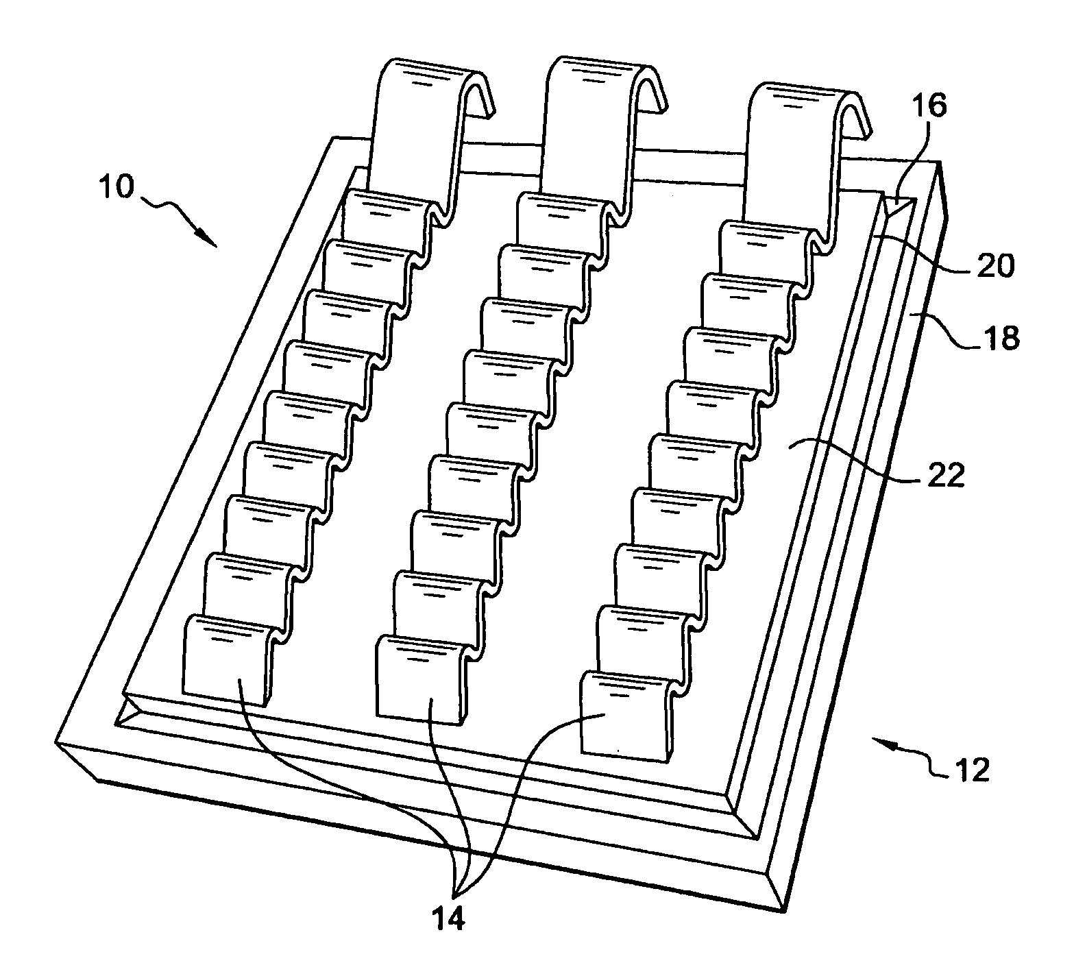
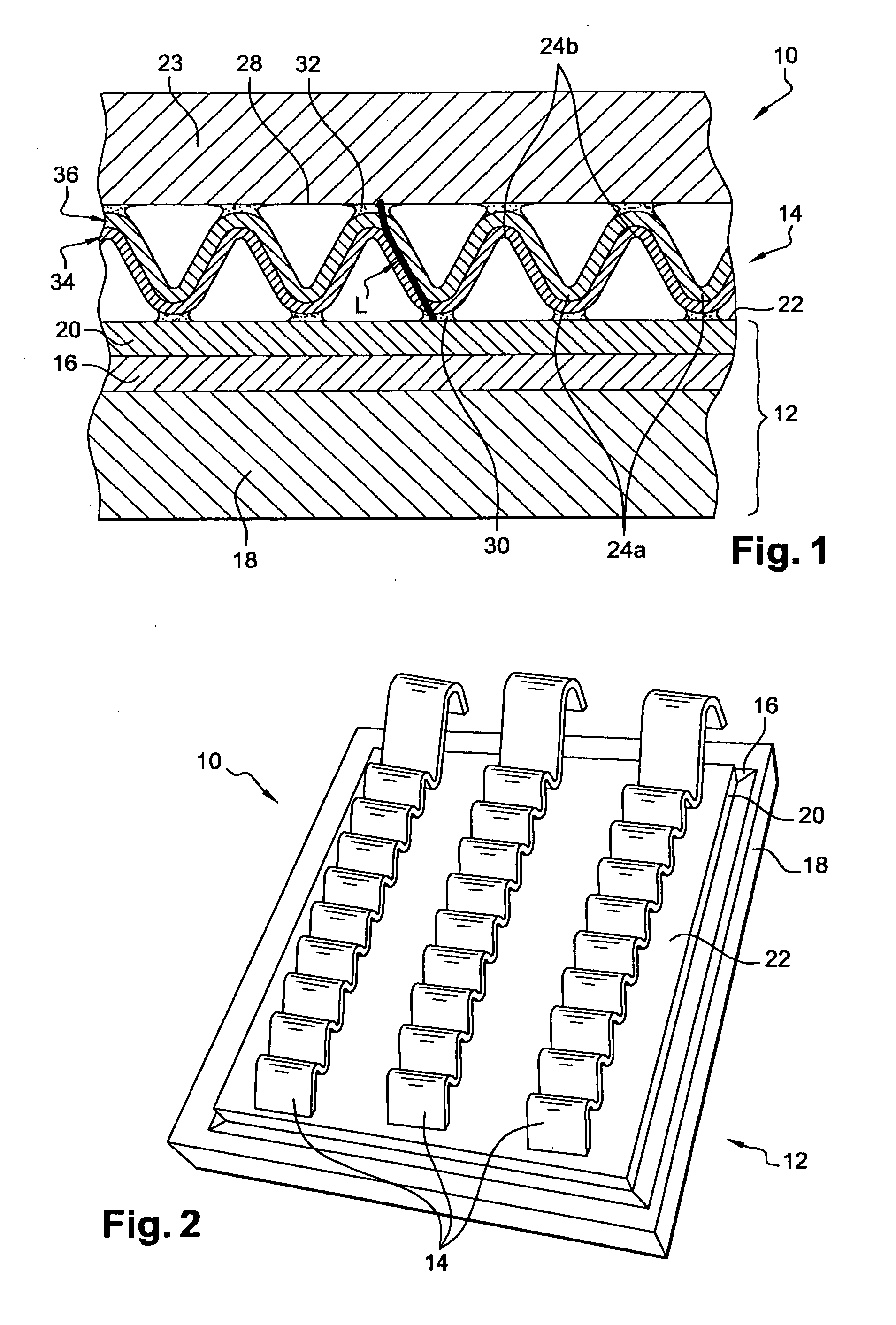
[0038]FIGS. 1 and 2 show a module 10 comprising an electronic component 12 and conductors 14, e.g. three conductors. In the example described, such a module 10 is a power module, e.g. used in a motor vehicle.

[0039]The electronic component 12 comprises a semiconductor chip 16 disposed on a substrate 18, the substrate forming both an electrical insulator and a heat dissipater. By way of example, the electronic component may be a non-integrated transistor such as a metal oxide on silicon field effect transistor (MOSFET) or a junction gate field effect transistor (JFET). This semiconductor chip 16 is covered in a metal film 20 that forms a conductive face 22 of the component 12, designed to be electrically connected to other elements, such as a connection member 23.

[0040]In this example, the connection member 23 is a connector that enables the electronic component 12 to be connected electrically to other electronic components.

[0041]The conductors 14 are generally in the form of tapes an...


PUM

PropertyMeasurementUnit
Pressureaaaaaaaaaa
Shapeaaaaaaaaaa
Electrical conductoraaaaaaaaaa

Abstract

The module is of the type comprising an electronic component provided with a conductive face that is electrically connected to a connection member of the component by means of a conductor that is corrugated at least in part so as to define an alternating sequence of oppositely-directed arcs, a first series of arcs being connected to the conductive face of the electronic component. The conductor also includes a second series of arcs opposite to the arcs of the first series and interposed between the arcs of the first series, the second series of arcs being connected to the conductive face of the connection member.

Description

[0001]The present invention relates to an electronic module and to a method of assembling such a module.[0002]The invention applies in particular to a power module for a motor vehicle, e.g. a module for performing switching functions.BACKGROUND OF THE INVENTION[0003]In the state of the art, and in particular from WO 2004 / 100258, there is known more particularly a module of the type comprising an electronic component provided with a conductive face that is electrically connected to a connection member of the component by means of a conductor that is corrugated at least in part so as to define an alternating sequence of oppositely-directed arcs, a first series of arcs being connected to the conductive face of the electronic component.[0004]By way of example, in such a module, the electronic component comprises a semiconductor chip arranged on a substrate. The conductive face is generally metallized, e.g. covered in a film of metal.[0005]By way of example, the connection member compris...

Claims


Application Information

Patent Timeline
IPC IPC(8): H01L23/48B32B37/00
CPCH01L2224/81801Y10T156/10H01L2924/01013H01L2924/01029H01L2924/01047H01L2924/01058H01L2924/01079H01L2924/01082H01L2924/13091H01L2924/19043H01L2924/01033H01L2924/014H01L24/40H01L24/41H01L24/84H01L2924/1306H01L2224/83801H01L2924/13062H01L2924/00H01L2224/84205H01L2924/00011H01L2224/37124H01L2224/37147H01L2224/371H01L24/37H01L2224/83205
Inventor MORELLE, JEAN-MICHELVIVET, LAURENTMEDINA, MATHIEULEON, RENAN
Owner VALEO ETUD ELECTRONIQUES
Why Eureka
Try Eureka