

Mechanically lockable hand switch
a hand switch and lockable technology, applied in the field of switches, can solve problems such as system faults, buttons that cannot be pressed down on the pushrod of the microswitch, buttons that cannot be tilted, etc., and achieve the effects of avoiding the disadvantages of the state of the art, preventing excessively heavy loading of buttons, and destroying solder joints
- Summary
- Abstract
- Description
- Claims
- Application Information
AI Technical Summary
Benefits of technology
Problems solved by technology
Method used
Image

Examples
Embodiment Construction
[0035]Identical parts or parts having the same action are denoted by the same references.
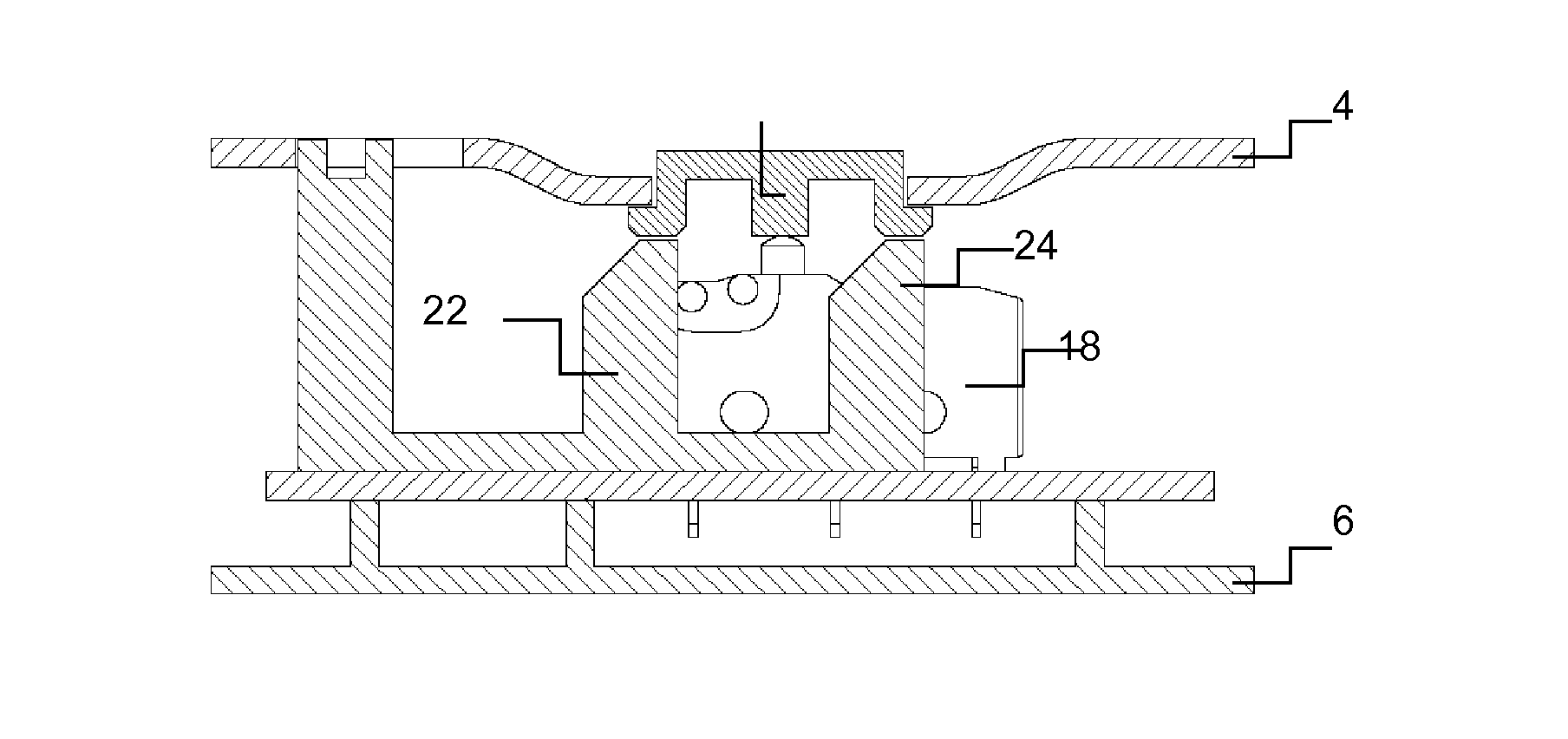
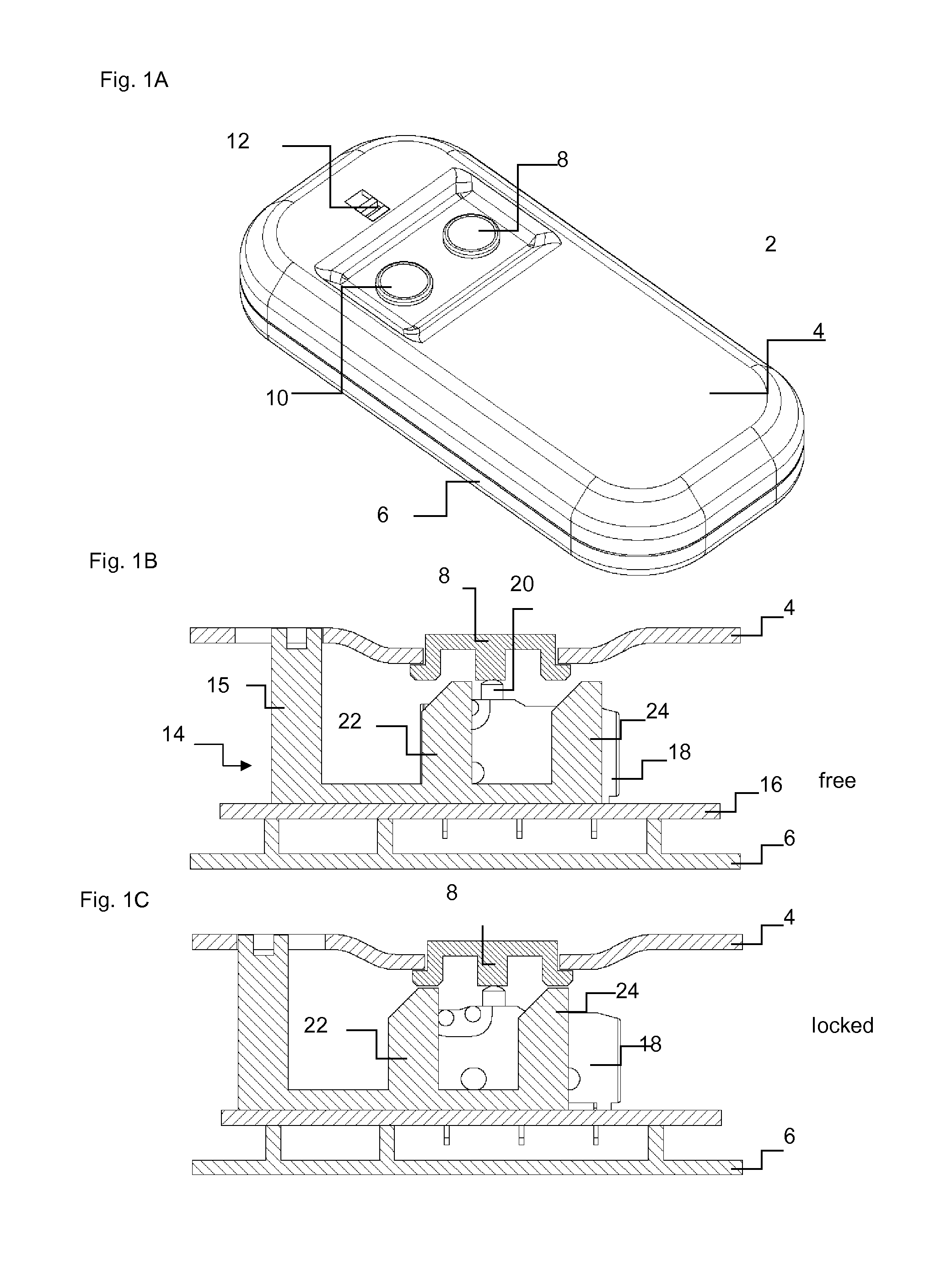
[0036]Accordingly the hand switch 2 shown as a perspective view in FIG. 1A comprises an elongate switch housing formed by an upper part 4 and a lower part 6 which are each in the form of a half-shell portion and the edges of which are joined together at the joint locations, enclosing a receiving space, preferably being connected releasably for repair purposes. The geometrical configuration of the hand switch is not relevant in the present case and here only represents a preferred embodiment.
[0037]The hand switch 2 comprises two buttons 8, 10 which respectively form a pair and which are intended to control an electric motor of a linear transmission for the chair in the one direction and in the opposite direction. Signal transmission from the hand switch to the electric motor is effected either by way of a cable (not shown) connected to the hand switch 2, or by way of wireless transmission.
[0038]T...
PUM
 Abstract
Description
Claims
Application Information