Visual distoration effects through translucent structures in design software

Active Publication Date: 2014-12-11
ICE EDGE BUSINESS SOLUTIONS
View PDF1 Cites 17 Cited by
  • Summary
  • Abstract
  • Description
  • Claims
  • Application Information

AI Technical Summary

Benefits of technology

[0011]Implementations of the present invention overcome one or more problems in the art with systems, methods, and apparatus configured to create translucent surfaces within a three-dimensional model. In particular, at least one implementation of the present invention renders a translucent surface that distorts a view of objects on an opposing side of the translucent surfac

Problems solved by technology

Additionally, the distortion effect can include blurrin

Method used


Image

  • Visual distoration effects through translucent structures in design software
  • Visual distoration effects through translucent structures in design software
  • Visual distoration effects through translucent structures in design software

Examples


Embodiment Construction

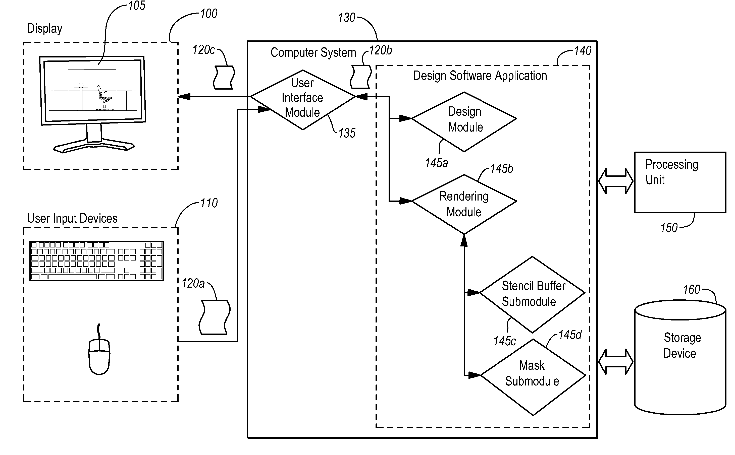
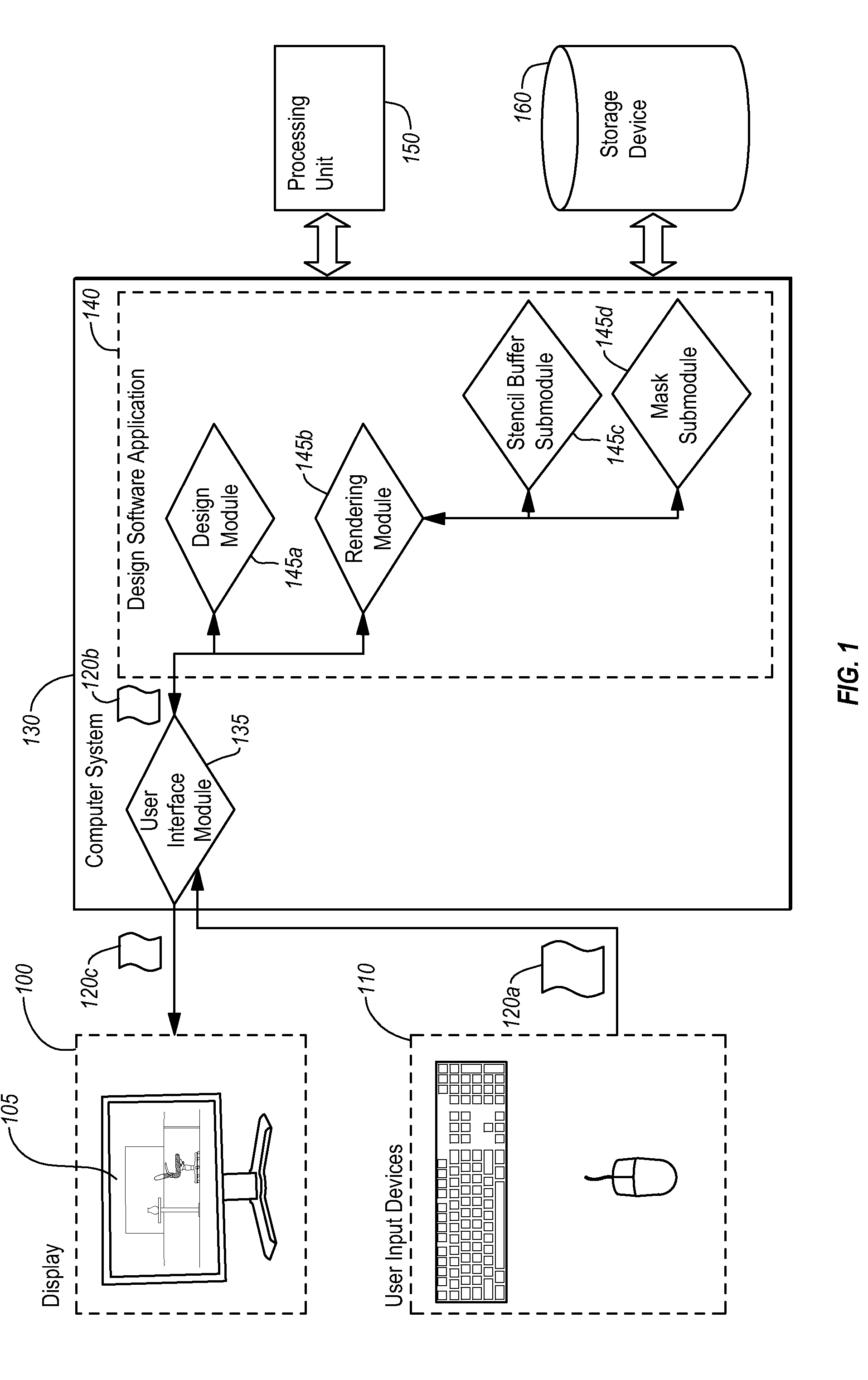
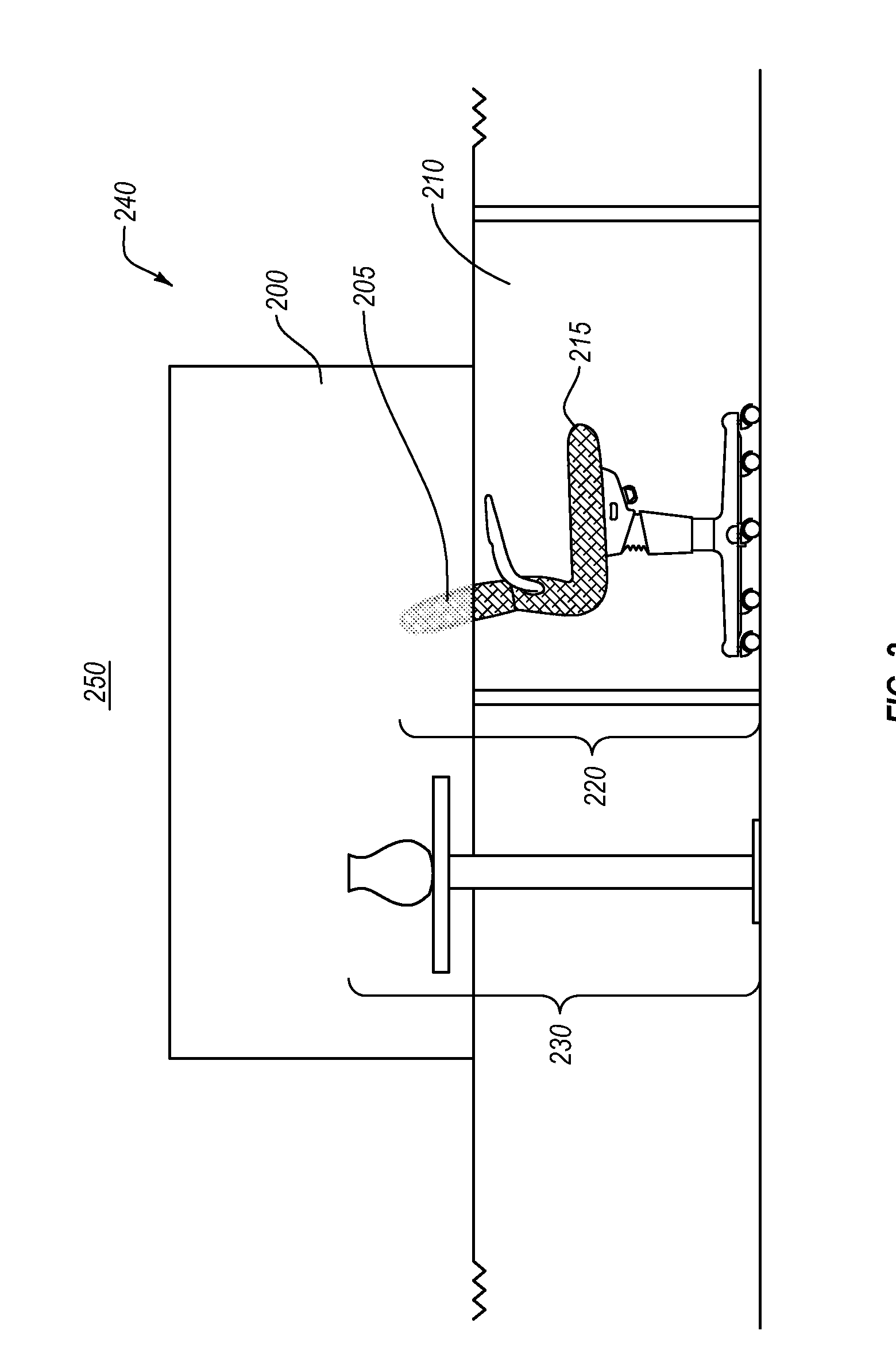
[0024]Implementations of the present invention extend to systems, methods, and apparatus configured to create translucent surfaces within a three-dimensional model. In particular, at least one implementation of the present invention renders a translucent surface that distorts a view of objects on an opposing side of the translucent surface. Additionally, in at least one implementation of the present invention, a distortion effect rendered with respect to a translucent surface depends upon the composition of the surface. Furthermore, at least one implementation of the present invention allows a user to create realistic visual distortion effects through translucent structures within a three-dimensional model.

[0025]For example, at least one implementation relates to displaying, in real-time, a three-dimensional model that comprises a translucent surface. As used within this application a translucent surface can comprise any surface that either distorts or partially blocks at least some...


PUM


Abstract

System, methods, and apparatus allow for creating translucent surfaces within a three-dimensional model. One or more implementations render a three-dimensional model of a layout of a design space within an architectural design environment. Additionally, one or more implementations identify a first portion of the three-dimensional model that is positioned behind a translucent surface within the three-dimensional model. Furthermore, one or more implementations render a visual distortion effect for the identified first portion of the three-dimensional model. Further still, one or more implementations display on a display device the three-dimensional model comprising the translucent surface, such that the three-dimensional model is displayed behind the translucent surface in a distorted form based on the rendered distortion effect.

Description

CROSS-REFERENCE TO RELATED APPLICATIONS[0001]The present invention is a 35 U.S.C. §371 U.S. National Stage of PCT Application No. PCT / US2013 / 024063 filed Jan. 31, 2013, entitled “Visual Distortion Effects through Translucent Structures in Design Software” the entire content of which is incorporated by reference herein.BACKGROUND OF THE INVENTION[0002]1. The Field of the Invention[0003]This present invention relates generally to computer-aided design or drafting software.[0004]2. Background and Relevant Technology[0005]Computer systems now play a critical role in building and / or architectural design. In particular, architects and interior designers (“or designers”) use a wide range of computer-aided design (CAD) software for designing the aesthetic as well as functional aspects of a given residential or commercial space. For example, a designer might use an architectural design program (e.g., a CAD program) to design the interior layout of an office building. The designer might then ...

Claims


Application Information

Patent Timeline
IPC IPC(8): G06T17/00
CPCG06T17/00G06T19/20G06T2210/04G06T2210/62G06T2219/2012G06T15/503
Inventor HOWELL, JOSEPH S.
Owner ICE EDGE BUSINESS SOLUTIONS
Why Eureka
Try Eureka