Vehicle barrier system with illuminating gate arm and method

a technology of vehicle barriers and light-emitting gates, applied in the field of vehicle barriers, can solve the problems of affecting the driver's ability to respond effectively, many vehicle barriers including such physical indicators provide limited use, and use of tape, markers or bright colors, etc., and achieve the effect of increasing visibility

Active Publication Date: 2014-12-11
GATEARM TECH
View PDF5 Cites 12 Cited by
  • Summary
  • Abstract
  • Description
  • Claims
  • Application Information

AI Technical Summary

Benefits of technology

[0007]The present invention overcomes the deficiencies of the known art and the problems that remain unsolved by providing a barrier system including a control system adapted to pivot a gate arm between a horizontal position and a vertical position to control the flow of vehicle or pedestrian traffic in control access areas such as parking lots, or parking garages. The gate arm includes inset channels for removeably receiving an array of light emitting diodes to increase visibility and alert drivers or pedestrians to the presence of a gate arm at night.

Problems solved by technology

However, many vehicle barriers including such physical indicators provide limited use.
Also, driver's often cannot see the physical indicators from greater distances, and as such, by the time the driver is alerted to the presence of the barrier, the vehicle is within close proximity of the barrier thereby further impairing the driver's ability to respond effectively.
The reflective tape, markers or bright colors, used on vehicle barriers, tend to fade over time, are often covered with debris, and provide limited visibility at night.
However, conventional vehicle barriers employing electronic light assemblies have certain drawbacks.
The single light assembly often provides limited visibility to drivers at night.
Further, maintenance of such light assemblies can be time consuming, burdensome and costly.
Prior art light assemblies tend to be bulky, heavy and are typically mounted on the external surface of vehicle barriers using large brackets, or a number of blots thus increasing both the costs and time in attaching and removing the light assemblies for each vehicle barrier.
Technicians are often forced to remove light assemblies from vehicle barriers to make necessary repairs as a result of traffic engaging the vehicle barriers and damaging the lighting devices.
Also, general maintenance of the light assemblies can be time consuming, and often results in the need for placing the vehicle barriers out of commission for a period of time while making necessary repairs, or replacing parts.

Method used


Image

  • Vehicle barrier system with illuminating gate arm and method
  • Vehicle barrier system with illuminating gate arm and method
  • Vehicle barrier system with illuminating gate arm and method

Examples


Embodiment Construction

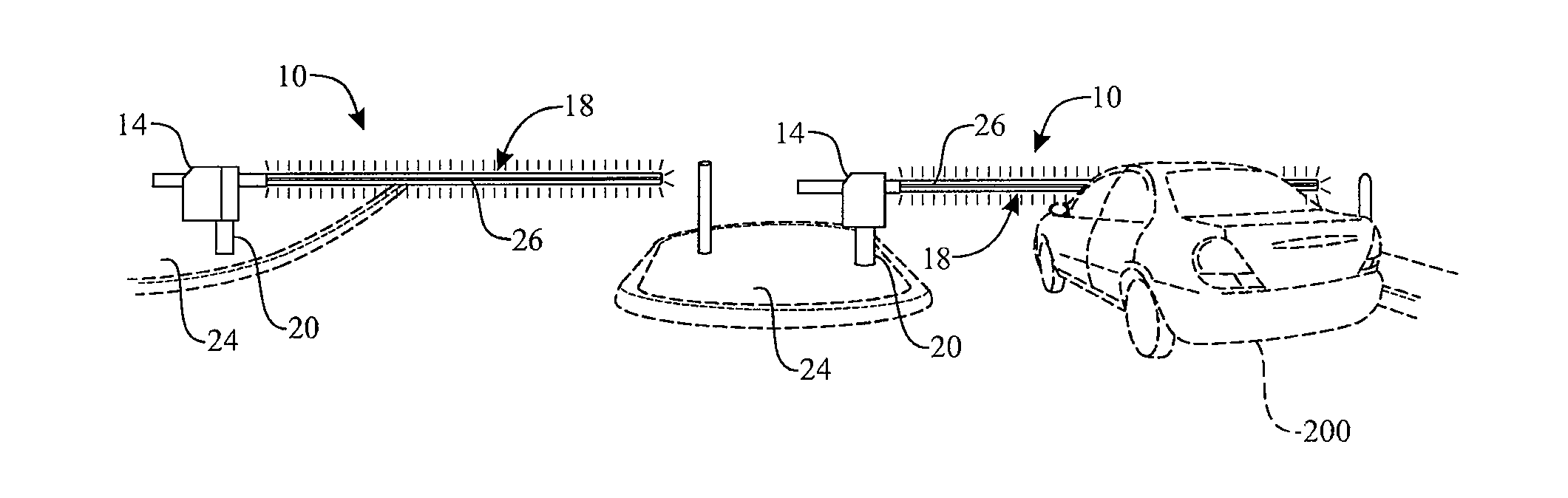
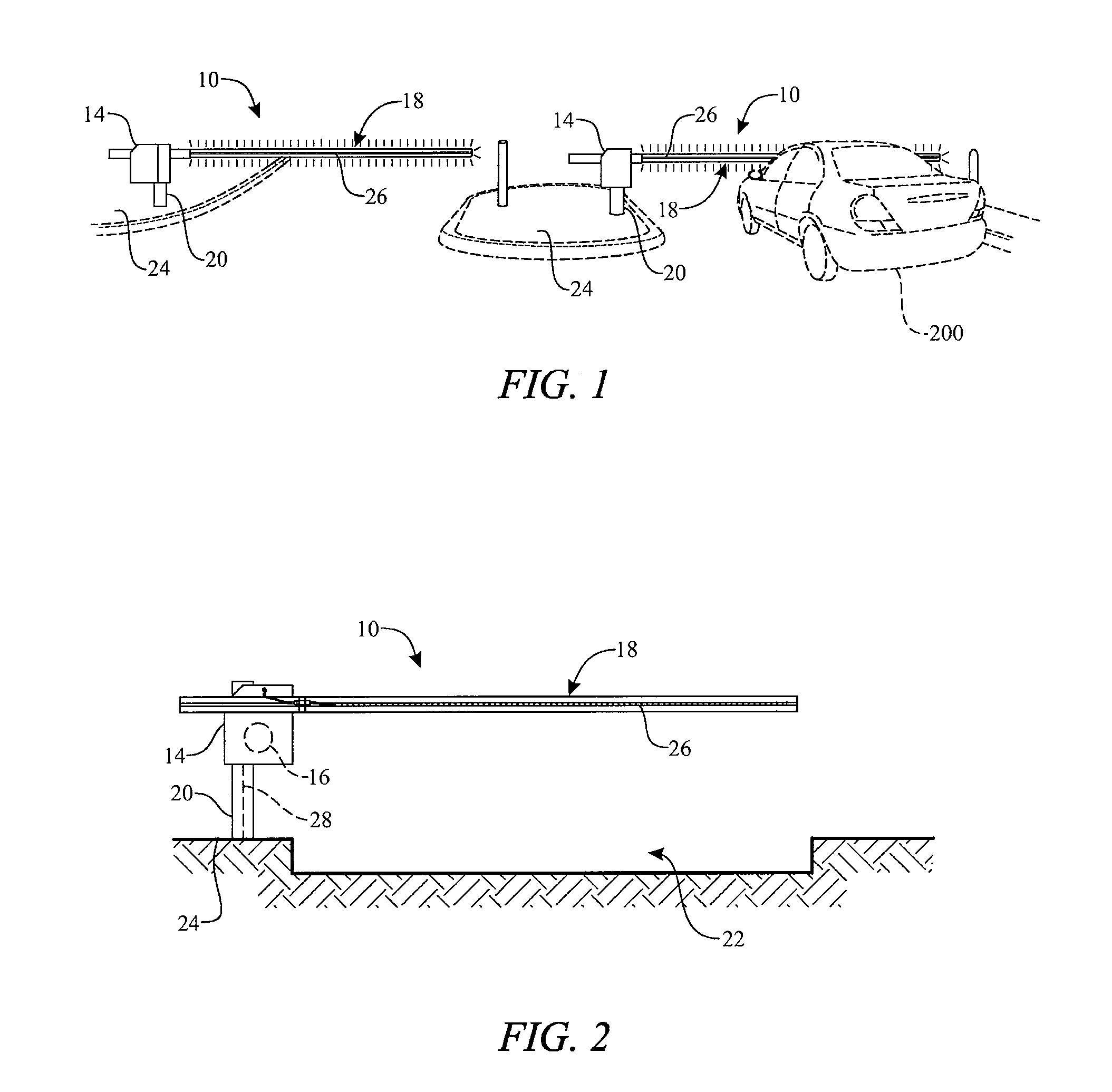
[0062]The following detailed description is merely exemplary in nature and is not intended to limit the described embodiments or the application and uses of the described embodiments. As used herein, the word “exemplary” or “illustrative” means “serving as an example, instance, or illustration.” Any implementation described herein as “exemplary” or “illustrative” is not necessarily to be construed as preferred or advantageous over other implementations. All of the implementations described below are exemplary implementations provided to enable persons skilled in the art to make or use the embodiments of the disclosure and are not intended to limit the scope of the disclosure, which is defined by the claims. For purposes of description herein, the terms “upper,”“lower,”“left,”“rear,”“right,”“front,”“vertical,”“horizontal,” and derivatives thereof shall relate to the invention as oriented in FIG. 1. Furthermore, there is no intention to be bound by any expressed or implied theory pres...


PUM


Abstract

The present invention is directed to a vehicle barrier system and method of use. The vehicle barrier system includes a control system adapted to pivot a gate arm between a horizontal position and a vertical position to control the flow of vehicle or pedestrian traffic in control access areas such as parking lots, or parking garages. The gate arm includes inset channels that are disposed along the longitudinal axis of the gate arm and configured to each remove ably receive an array of light emitting diodes to increase visibility and alert drivers or pedestrians to the presence of a gate arm.

Description

CROSS-REFERENCE TO RELATED APPLICATION[0001]In accordance with 37 C.F.R. §1.76, a claim of priority is included in an Application Data Sheet filed concurrently herewith. Accordingly, the present invention claims priority as a continuation of U.S. patent application Ser. No. 13 / 803,093, filed Mar. 14, 2013, entitled VEHICLE BARRIER SYSTEM WITH ILLUMINATING GATE ARM AND METHOD, which claims priority of U.S. Provisional Patent Application No. 61 / 654,280, filed on Jun. 1, 2012. The contents of which the above referenced applications are incorporated hereby by reference in their entirety.FIELD OF THE INVENTION[0002]The present invention relates generally to barrier systems. More particularly, the present disclosure relates to a vehicle barrier system and method where the barrier system includes a control system adapted to pivot a gate arm between a guarded and unguarded position to provide controlled access of vehicle traffic in restricted areas such as parking lots, parking garages, or ...

Claims


Application Information

Patent Timeline
Patent Type & Authority Applications(United States)
IPC IPC(8): E01F13/06F21S4/00
CPCE01F13/06F21Y2103/003F21S4/003B61L29/04B61L29/24F21S4/20F21Y2103/10F21Y2115/10
Inventor LUMSDEN, RUSSELSIRJU, JAIKEESHANFORTNEY, BRYCE CHARLES
Owner GATEARM TECH
Why Eureka
Try Eureka