Control system

a control system and pedal drive technology, applied in the field of electric vehicles, can solve the problems of reducing the potential operation range of the vehicle, excessive vehicle speed and/or unnecessary electric power consumption, and inability to supply electrical power to the electric motor too much,

Inactive Publication Date: 2014-12-11
HOGANAS AB
View PDF1 Cites 11 Cited by
  • Summary
  • Abstract
  • Description
  • Claims
  • Application Information

AI Technical Summary

Problems solved by technology

However, it is important to ensure that the amount of electrical power supplied to the electric motor cannot be too great under certain circumstances so as to permit the speed of the vehicle to become excessive.
In addition, it should be ensured that the system will not permit the user to bypass the control and to operate the electric motor manually, which may also result in excessive speed of the vehicle and / or unnecessary consumption of electric power which would reduce potential operation range of the vehicle.
However, the user of such a vehicle cannot set or fine-tune the proportion between power output from the electric motor and his / her own muscle power.
However, the user of such a vehicle is not able to control the amount of power he has to produce in relation to the electric auxiliary motor.

Method used


Image

  • Control system
  • Control system
  • Control system

Examples


first embodiment

[0035]Accordingly, in a first embodiment, the disclosure provides a method for controlling and regulating an electrical auxiliary motor suitable for a pedal-driven vehicle comprising a crank axle, such as a bicycle, in such a way that said electrical auxiliary motor assists a user in rotating said crank axle by muscular force, and comprising the steps of[0036]a) receiving information about the specific torque TPSet said user would like to generate when rotating said crank axle by muscular force;[0037]b) determining the actual torque TP generated by the user on the crank axle;[0038]c) for each TP, adjusting the torque generated by the electrical auxiliary motor TM in such a way that:[0039]TM is increased in case TP is higher than TPSet;[0040]TM is not changed in case TP is equal to TPSet;[0041]TM is reduced in case TP is lower than TPSet; and[0042]TM is 0 in case TP is 0.

[0043]As disclosed herein, the terms “vehicle” or “pedal-driven vehicle comprising a crank axle” both typically re...

second embodiment

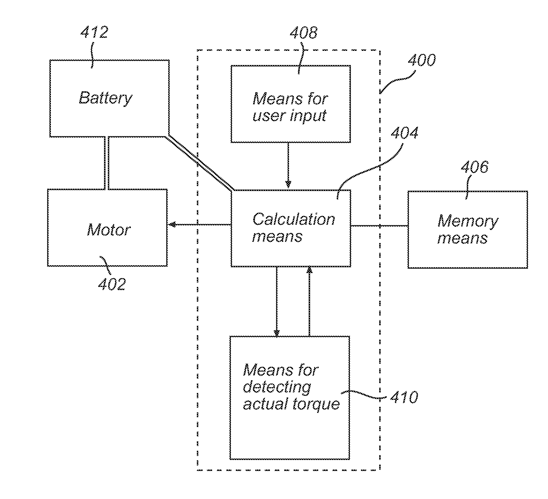
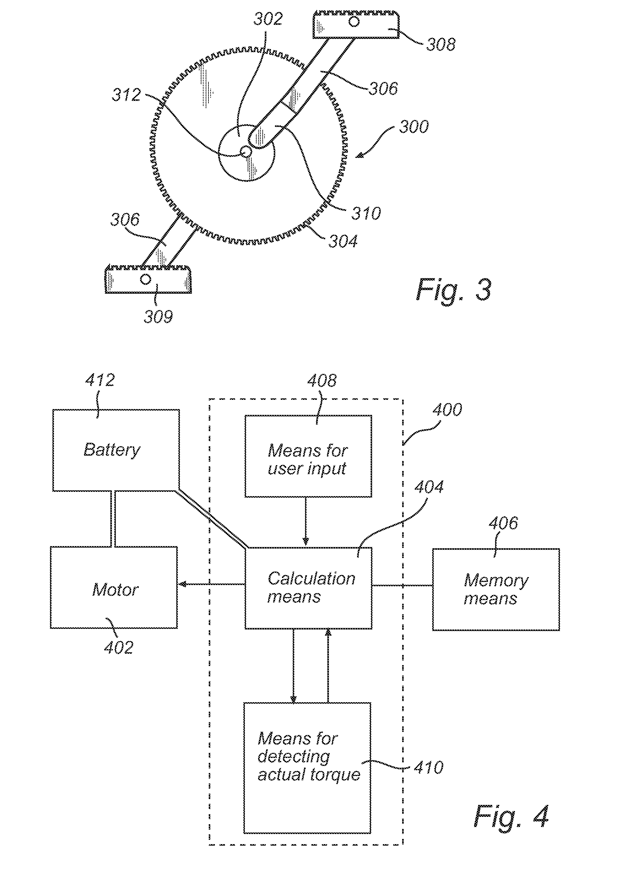
[0048]In a second embodiment, the disclosure provides a system for controlling and regulating an electrical auxiliary motor suitable for a pedal-driven vehicle comprising a crank axle, such as a bicycle, said system comprising:[0049]a) a means for receiving information about the specific torque TPSet a user would like to generate when rotating said crank axle by muscular force;[0050]b) a means for determining the actual torque TP generated by the user on the crank axle; and[0051]c) a control and calculation means;[0052]wherein[0053]said means for receiving information about the specific torque TPSet is set up to forward said information to said control and calculation means;[0054]said means for determining the actual torque TP is set up to forward information about said torque to said control and calculation means;[0055]said control and calculation means is set up to receive information about the specific torque TPSet a user would like to generate when rotating said crank axle by mu...


PUM


Abstract

A method for controlling and regulating an electrical auxiliary motor suitable for a pedal-driven vehicle including a crank axle, such as a bicycle, in such a way that said electrical auxiliary motor assists a user in rotating said crank axle by muscular force, the method including: a) receiving information about the specific torque TPSet said user would like to generate when rotating said crank axle by muscular force; b) determining the actual torque TP generated by the user on the crank axle; and c) for each TP, adjusting the torque generated by the electrical auxiliary motor TM in such a way that: TM is increased in case TP is higher than TPSet; TM is not changed in case TP is equal to TPSet; TM is reduced in case TP is lower than TPSet; and TM is 0 in case TP is 0.

Description

TECHNICAL FIELD[0001]Embodiments of the disclosure relate to the field of vehicles, and more specifically to the field of power-assisted pedal-driven vehicles comprising a crank axle, and an electrical auxiliary motor such as electrically assisted bicycles. The disclosure provides a method for controlling an electrical auxiliary motor, a system for implementing said method, as well as a power-assisted pedal-driven vehicle comprising the system.TECHNICAL BACKGROUND[0002]It is known to provide a manually powered vehicle with an electric auxiliary motor so as to assist the user in the manual propulsion of the vehicle. U.S. Pat. No. 5,370,200 shows a manually powered vehicle such as a bicycle wherein there is provided an electrical auxiliary motor for assisting the user in the powering of the vehicle. This type of mechanism includes an arrangement that senses the manual input force or torque exerted by the occupant and then powers an electric motor by connecting it to a battery in such ...

Claims


Application Information

Patent Timeline
Patent Type & Authority Applications(United States)
IPC IPC(8): H02P29/00G05D17/02G05B15/02
CPCH02P29/00G05D17/02G05B15/02B62M6/65B62M6/45
Inventor KRUSE, RAISSA
Owner HOGANAS AB
Why Eureka
Try Eureka