Vehicle, particularly a bicycle, comprising an electrical auxiliary drive

Active Publication Date: 2017-01-10
STROTHMANN ROLF
View PDF13 Cites 1 Cited by
  • Summary
  • Abstract
  • Description
  • Claims
  • Application Information

AI Technical Summary

Benefits of technology

[0004]The invention is based on the goal of creating a simply configured vehicle of the type indicated above whic

Problems solved by technology

The reduced drive force to be expended by the rider allows higher riding speeds; without appropriate devices for changin

Method used


Image

  • Vehicle, particularly a bicycle, comprising an electrical auxiliary drive
  • Vehicle, particularly a bicycle, comprising an electrical auxiliary drive

Examples


Embodiment Construction

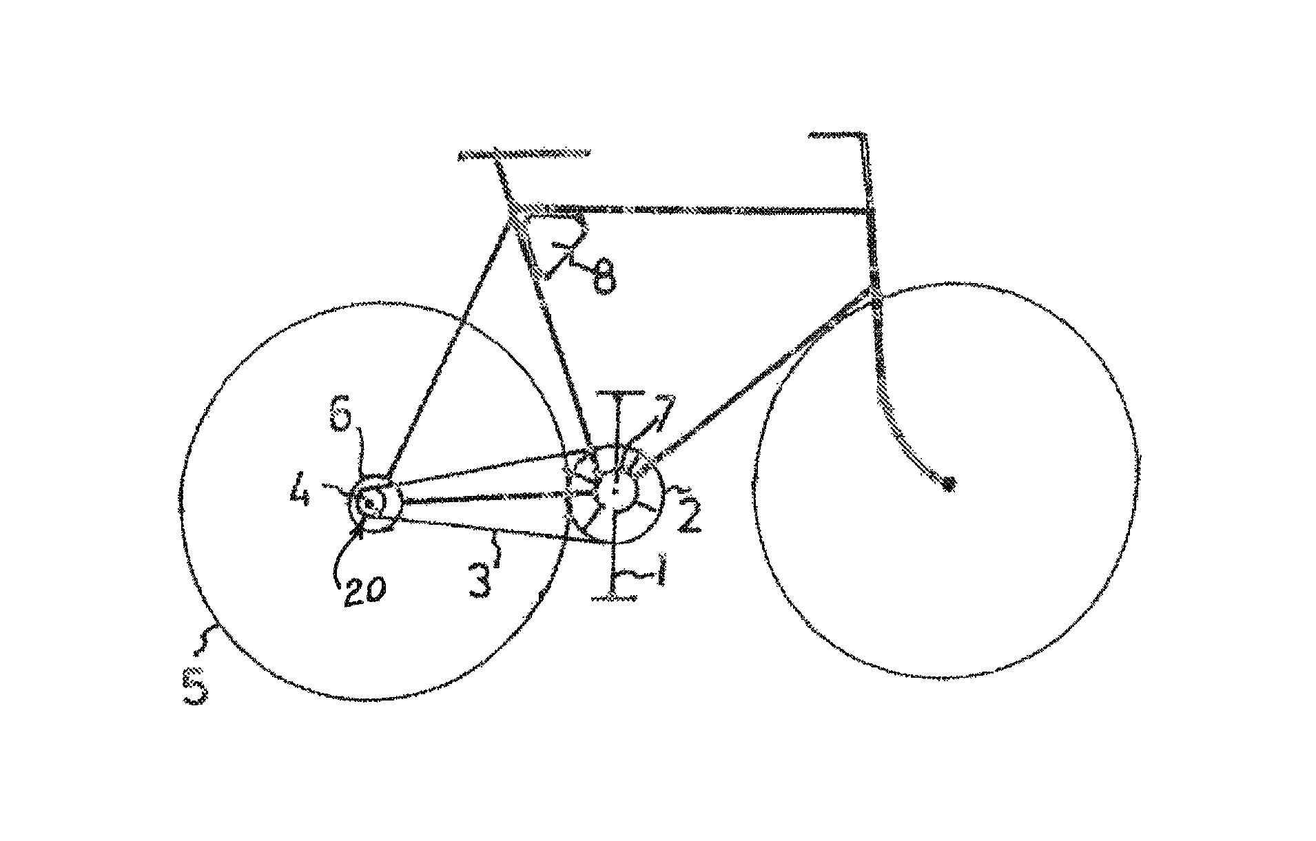
[0024]A bicycle shown in FIG. 1 comprises a crank drive, which is formed in the usual manner by pedal cranks 1, a main sprocket 2, a chain 3, and a rear sprocket 4. The rear sprocket 4 is in drive connection with the rear wheel 5 of the bicycle by way of a freewheel 20.

[0025]Coaxial to the rear sprocket 4 is an electrical machine 6, as a component of an electrical auxiliary drive; in the exemplary embodiment shown here, this machine forms a hub motor. The rotor of the electrical machine 6 is rigidly drive-connected to the wheel 5 in such a way that the machine can transmit both drive and braking torques to the wheel.

[0026]Another electrical machine 7 is arranged coaxial to the rotational axis of the pedal cranks 1. Its rotor is rigidly drive-connected to the main sprocket 2. Instead of the arrangement in which the rotor is coaxial to the rotational axis of the pedal crank, an arrangement in which the electrical machine 7 is offset from this rotational axis would also be possible, in...


PUM


Abstract

A vehicle, particularly a bicycle, including a crank drive that is to be actuated by muscular force and that is disconnectably drive-connected to at least one driven wheel, and also including an electrical auxiliary drive for assisting the crank drive. The vehicle can be driven solely by the auxiliary drive when the drive connection between the crank drive and the wheel is disconnected. In addition, a control device for the auxiliary drive is preferably connected to a sensor which detects the crank rotational speed.

Description

[0001]The present application is a 371 of International application PCT / DE2013 / 100139, filed Apr. 12, 2013, which claims priority of DE 10 2012 104 150.4, filed May 11, 2012, the priority of these applications is hereby claimed and these applications are incorporated herein by reference.BACKGROUND OF THE INVENTION[0002]The invention pertains to a vehicle, especially a bicycle, with a muscle-powered crank drive disconnectably drive-connected to at least one drive wheel, and also with an electrical auxiliary drive to assist the crank drive.[0003]Bicycles of this type, which can be ridden like a normal bicycle but for which an electrical auxiliary drive ensures that the force to be expended to push the pedals is kept within limits, are known through prior use. The reduced drive force to be expended by the rider allows higher riding speeds; without appropriate devices for changing the gear ratio, however, such higher speeds are associated with rapid leg movements, which are perceived as...

Claims


Application Information

Patent Timeline
IPC IPC(8): B62M6/45B62M6/50
CPCB62M6/50B62M6/45
Inventor STROTHMANN, ROLF
Owner STROTHMANN ROLF
Why Eureka
Try Eureka