RFID tag for a personal care appliance

Inactive Publication Date: 2014-12-18
LOREAL SA
View PDF1 Cites 4 Cited by
  • Summary
  • Abstract
  • Description
  • Claims
  • Application Information

AI Technical Summary

Benefits of technology

[0005]Accordingly, an RFID tag for a personal care appliance comprises: a laminated RFID tag mountable to a part of a personal care appliance, w

Problems solved by technology

Such RFID tags when used in corrosive or wet locations are subject to failure by virtue of separation from the surface on which they are mounted and/or separation of layers within the RFID tag.
The square corner RFID tag shown in FIG. 1 is thus typically not suitable or recommended for use in challenging conditions, such as for instance in a facial cleansing personal appliance, as failure of the adhesive bond is common

Method used


Image

  • RFID tag for a personal care appliance
  • RFID tag for a personal care appliance
  • RFID tag for a personal care appliance

Examples


Embodiment Construction

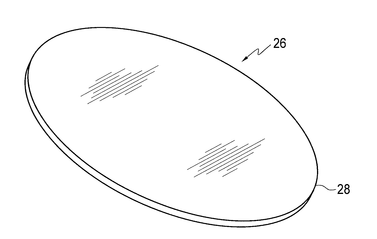
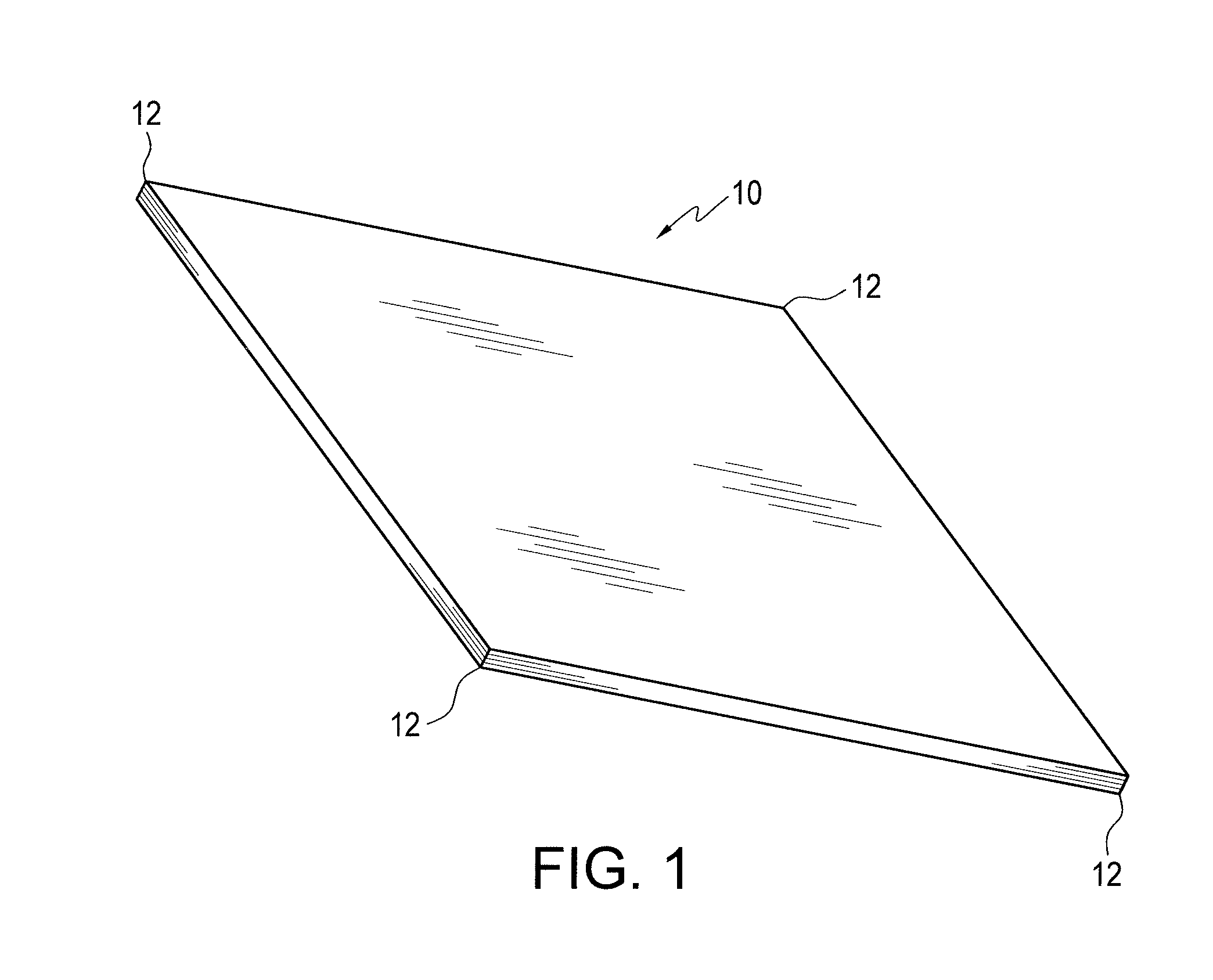
[0012]The present invention involves a new edge configuration for an RFID tag which is designed to operate well in challenging environmental conditions. It has been discovered by the inventors herein that the conventional laminated RFID tags often become delaminated due to failure of the adhesive bond between the tag and the mounting surface and the laminate structure itself in challenging conditions, such as those conditions which produce high solvent exposure and where there is vibration, with rinsing and drying operational cycles. It has further been discovered that with conventional RFID tags, delamination frequently begins at the existing sharp corners (12-12 in FIG. 1) of a tag because sharp corners of the tag are more susceptible to absorbance of solvents and therefore more susceptible in initial separation or delamination, leading to a more general failure of the lamination structure and / or the entire adhesive bond of the tag. FIG. 5 shows the top left portion (1 cm×1 cm) of...


PUM


Abstract

The laminated RFID tag, mountable to a part of a personal care appliance, has rounded corners or a round peripheral edge, which is adapted to prevent absorption of water or other solvents.

Description

TECHNICAL FIELD[0001]This invention relates generally to RFID (radio frequency identification) tags, and more specifically relates to such tags designed to be used in challenging environmental conditions, such as in a facial (skin) cleansing appliance.BACKGROUND OF THE INVENTION[0002]RFID tags, usually in laminated form, are typically approximately 0.0007 inches thick, and typically have a square or rectangular configuration with sharp corners. An example of a conventional laminated RFID tag is shown in FIG. 1 at 10. Laminated RFID tags are used in a variety of applications, including wireless identification of workpieces. Such RFID tags when used in corrosive or wet locations are subject to failure by virtue of separation from the surface on which they are mounted and / or separation of layers within the RFID tag. Separation, i.e. delamination, often accelerates following some degree of initial delamination of the tag. The square corner RFID tag shown in FIG. 1 is thus typically not ...

Claims


Application Information

Patent Timeline
IPC IPC(8): G06K19/077
CPCG06K19/07773G06K19/07758G06K19/07724
Inventor GREZ, JOSEPHGUNDERSON, DAVID
Owner LOREAL SA
Why Eureka
Try Eureka