
3D image display device and method thereof

a display device and image technology, applied in the field of three-dimensional (3d) image display techniques, can solve the problems of user discomfort, image overlap, high cost, etc., and achieve the effect of removing bulkiness and high cos

Inactive Publication Date: 2014-12-18
NAT TAIWAN UNIV
View PDF15 Cites 6 Cited by
  • Summary
  • Abstract
  • Description
  • Claims
  • Application Information

AI Technical Summary

Benefits of technology

The present invention provides glasses for viewing 3D images that produce left-eye and right-eye images with different wavelength ranges. The glasses have light filtering units on the left and right lenses that filter out the right-eye image and only allow the left-eye image to pass through when a user looks at a 3D image from a certain angle. This prevents image overlap and avoids the use of active glasses that are bulky and expensive.

Problems solved by technology

Double-panel displays uses two display panels each showing the image of one of the left and right eyes to achieve a 3D image display effect; the cost of which is higher.
However, the disadvantage of the polarized glasses is that when the head tilts or rotates, the polarized glasses cannot complete filter out the light in the other direction, so the eyes will see lights that are not completely filtered, resulting in images overlap and causing discomfort in users.
However, active glasses themselves require the use of electricity, making active glasses heavier, and the manufacturing cost relatively higher.
Therefore, how to reduce the manufacturing costs of traditional 3D image displays and improve the shortcomings of polarized glasses has become an issue to be solved by one with ordinary skills in the art.

Method used


Image

  • 3D image display device and method thereof
  • 3D image display device and method thereof
  • 3D image display device and method thereof

Examples


first embodiment

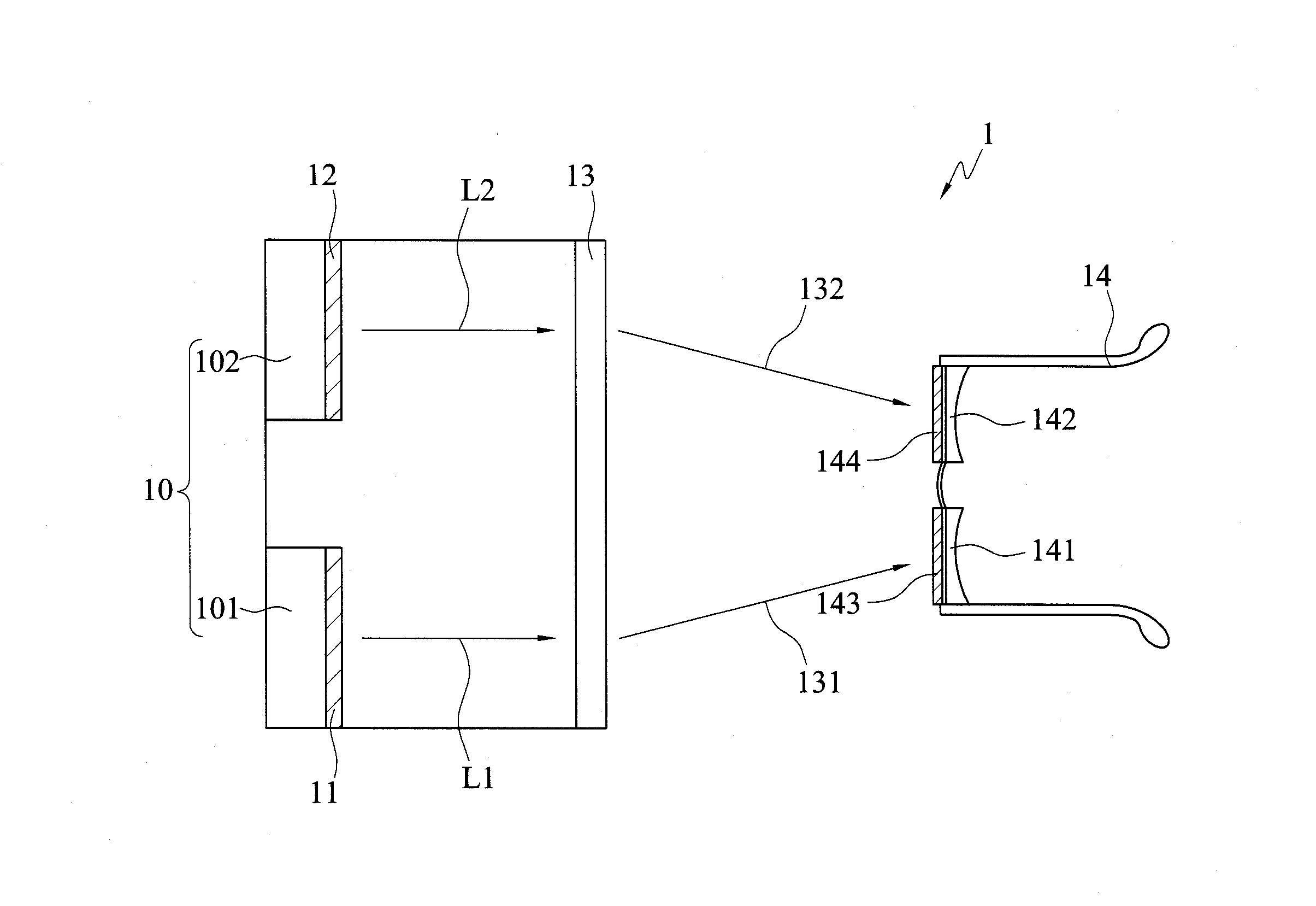
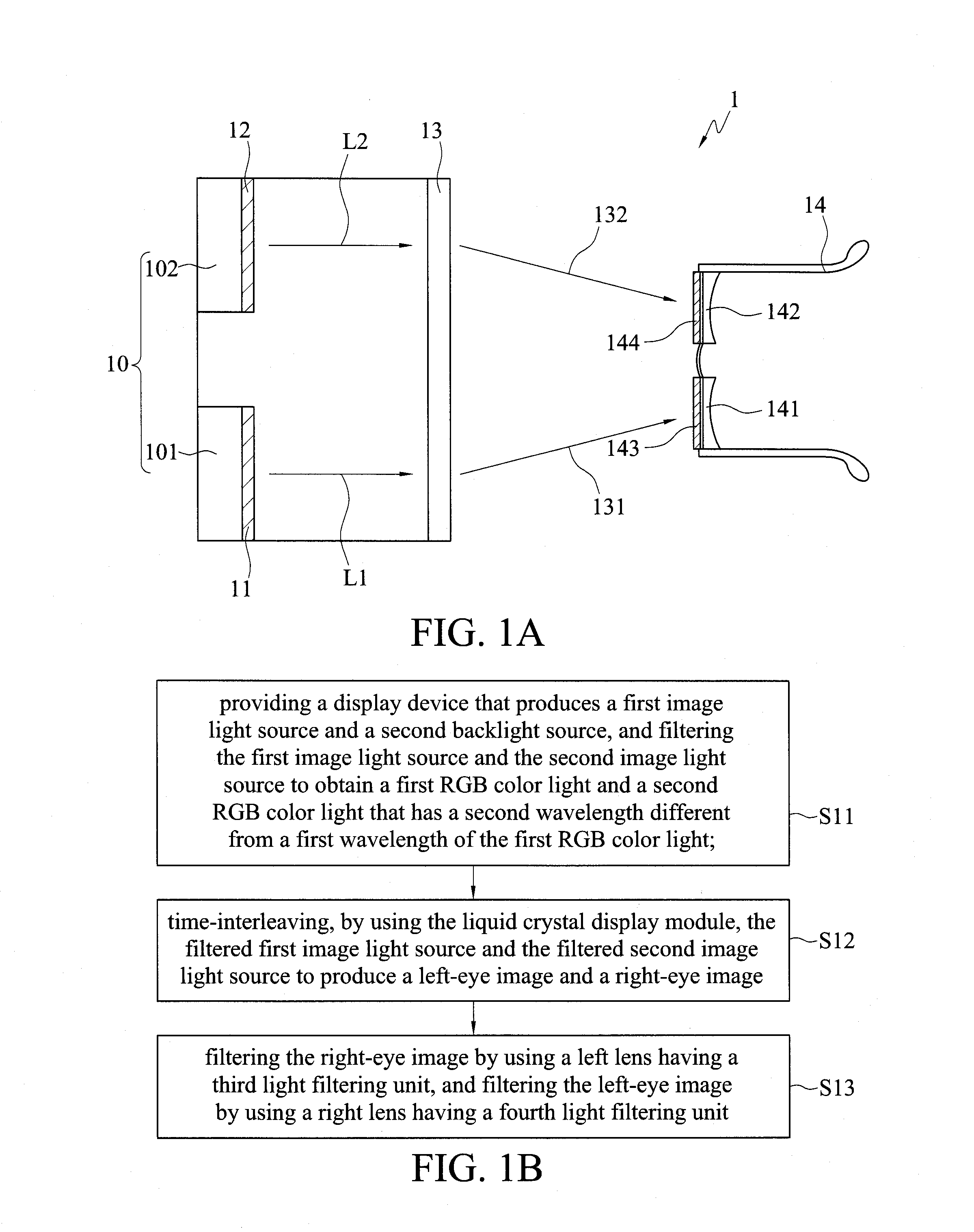
[0037]Referring to FIG. 1A, a three-dimensional (3D) image display device 1 in accordance with the present invention is shown. The 3D image display device 1 includes a light source module 10, a first light filtering unit 11, a second light filtering unit 12, a liquid crystal display module 13, and a pair of glasses 14.

[0038]The light source module 10 has a first backlight source 101 and a second backlight source 102. The first backlight source 101 generates and outputs a first image light source L1. The second backlight source 102 generates and outputs a second image light source L2. Since the wavelength range of the first image light source L1 generated by the first backlight source 101 is the same as that of the second image light source L2 generated by the second backlight source 102, the first backlight source 101 of the light source module 10 incorporates the first light filtering unit 11, while the second backlight source 102 incorporates the second light filtering unit 12. Th...

second embodiment

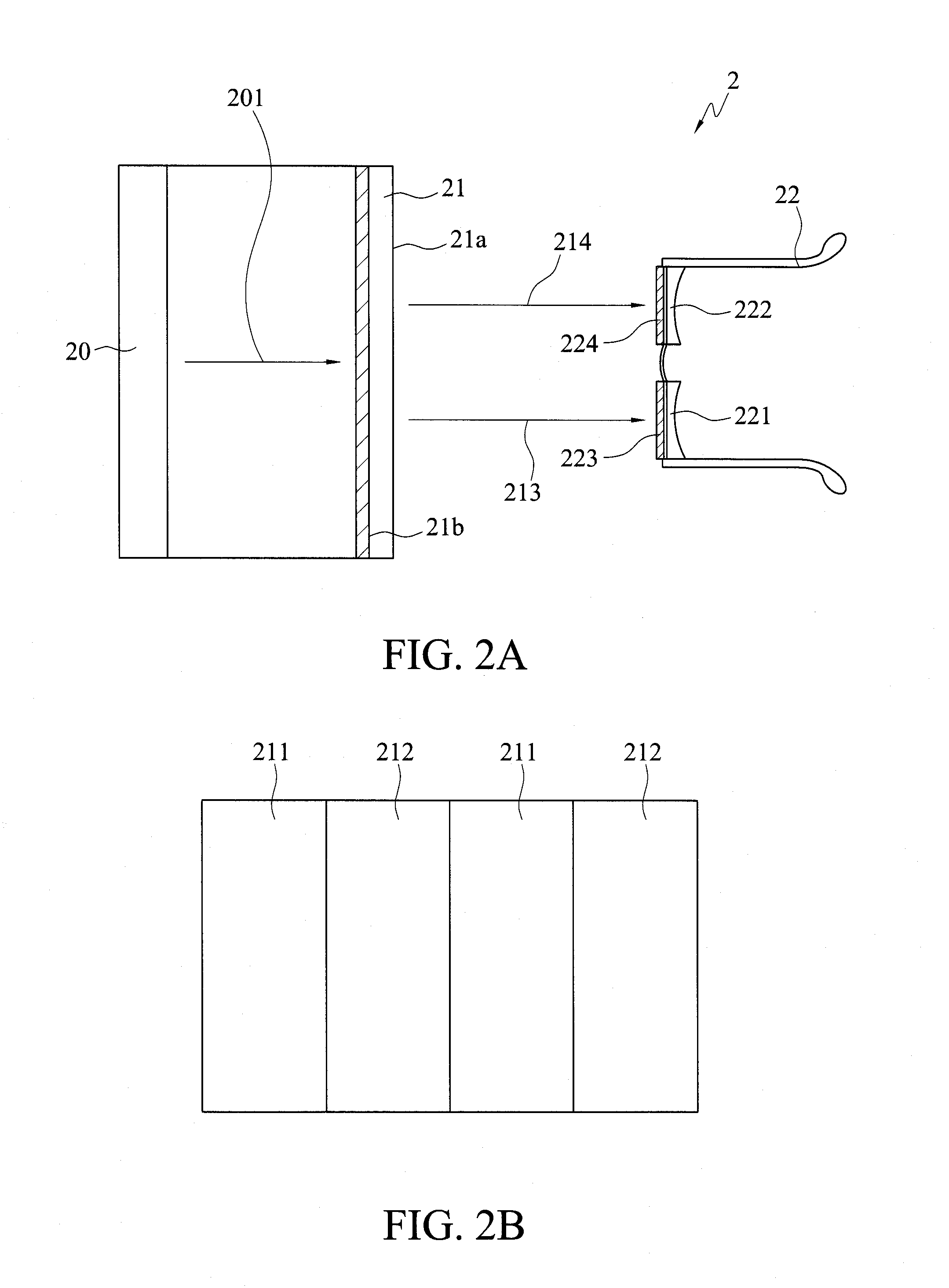
[0042]Referring now to both FIGS. 2A and 2B, a 3D image display device 2 in accordance with the present invention is shown in FIG. 2A, and a distribution of first light filtering units and second light filtering units is shown in FIG. 2B. The 3D image display device 2 includes a light source module 20, a liquid crystal display module 21 and a pair of glasses 22.

[0043]The light source module 20 generates an image light source 201. The liquid crystal display module 21 generates an image by using the image light source 201. The liquid crystal display module 21 is provided with first light filtering units 211 and second light filtering units 212. The first light filtering units 211 are used for filtering the image light source 201 to obtain a first RGB color light, so that the liquid crystal display module 21 correspondingly produces a left-eye image 213. The second light filtering units 212 are used for filtering the image light source 201 to obtain of a second RGB color light, so that...

third embodiment

[0049]Referring now to both FIGS. 3A and 3B, a 3D image display device 3 in accordance with the present invention is shown in FIG. 3A, and a distribution of a first light source and a second light source is shown in FIG. 3B. The 3D image display device 3 includes an active light emitting panel 31 and a pair of glasses 32. The active light emitting panel 31 is used for displaying images. The glasses 32 are used for receiving the images.

[0050]As shown in FIG. 3B, the active light emitting panel 31 has a plurality of pixel modules 311. Each of the pixel modules 311 includes a first light source 311a and a second light source 311b. The first light source 311a is used for generating a first RGB color light, and the second light source 311b is used for generating a second RGB color light. The active light emitting panel 31 produces from the first RGB color light of the first light sources 311a a first image 312 corresponding to the left eye of a user, and from the second RGB color light o...


PUM


Abstract

A three-dimensional (3D) image display device and a method thereof are provided. A first light filtering unit obtains a first RGB color light filtered from a first image, and a second light filtering unit obtains a second RGB color light filtered from a second image, to produce a left-eye image and a right-eye image, respectively, or an active light emitting panel produces a first image and a second image of different wavelengths. When a user is wearing glasses with different light filters on the left and right lenses to filter out the right-eye image and the left-eye image, respectively, the user receives 3D visual effects from the images.

Description

BACKGROUND OF THE INVENTION[0001]1. Field of the Invention[0002]The present invention relates to three-dimensional (3D) image display techniques, and, more particularly, to a 3D image display device and a method thereof.[0003]2. Description of Related Art[0004]In recent years, as the quality of life improves, the trend of display technology has been moving from flat panel display technology to three-dimensional (3D) image display technology. Since the distance between the right eye and the left eye of a human being is about 6.5 cm, the viewing angles are slightly different when looking at an object and the received images will have slight differences. The so-called 3D image display technology utilizes the visual difference between the two eyes to provide two different images to produce a three-dimensional sense.[0005]Most of the current 3D image display technologies require users to wear polarized glasses in order to create a three-dimensional effect from images generated by the 3D ...

Claims


Application Information

Patent Timeline
IPC IPC(8): H04N13/04
CPCH04N13/0422H04N13/341H04N13/324
Inventor LIN, CHING-FUH
Owner NAT TAIWAN UNIV
Learn More