
Milli-meter-wave-wireless-interconnect (m2w2-interconnect)method for short-range communications with ultra-high data rate capability

a technology of ultra-high data rate and wireless interconnection, which is applied in the direction of duplex signal operation, digital transmission, near-field system using receivers, etc., can solve the problems of increasing the complexity of the architecture and overall power consumption, limiting the bandwidth, power and latency of the on-chip interconnect, and remaining non-scalable and non-reconfigurable. , to achieve the effect of high data rate capability

Active Publication Date: 2014-12-18
RGT UNIV OF CALIFORNIA
View PDF2 Cites 3 Cited by
  • Summary
  • Abstract
  • Description
  • Claims
  • Application Information

AI Technical Summary

Benefits of technology

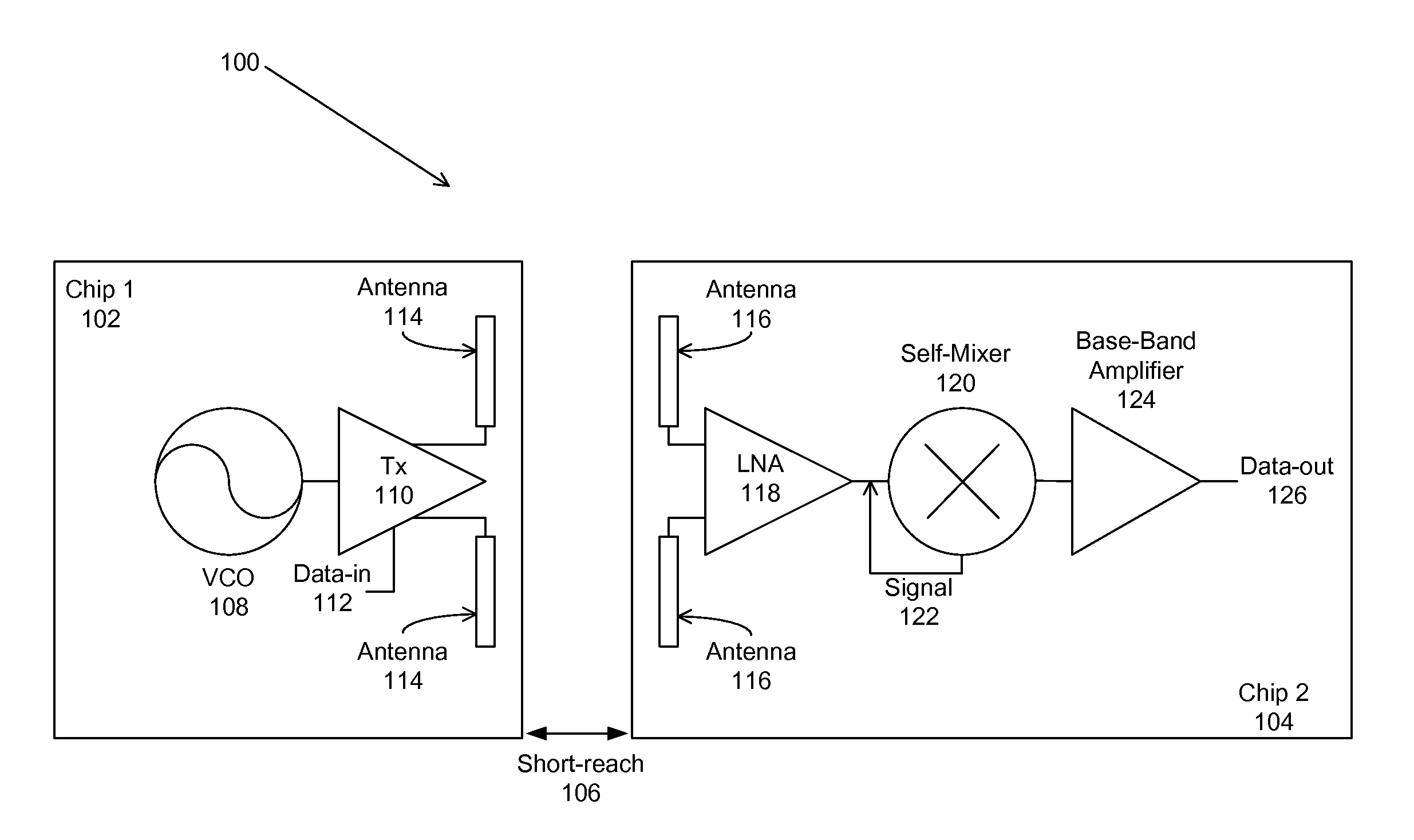
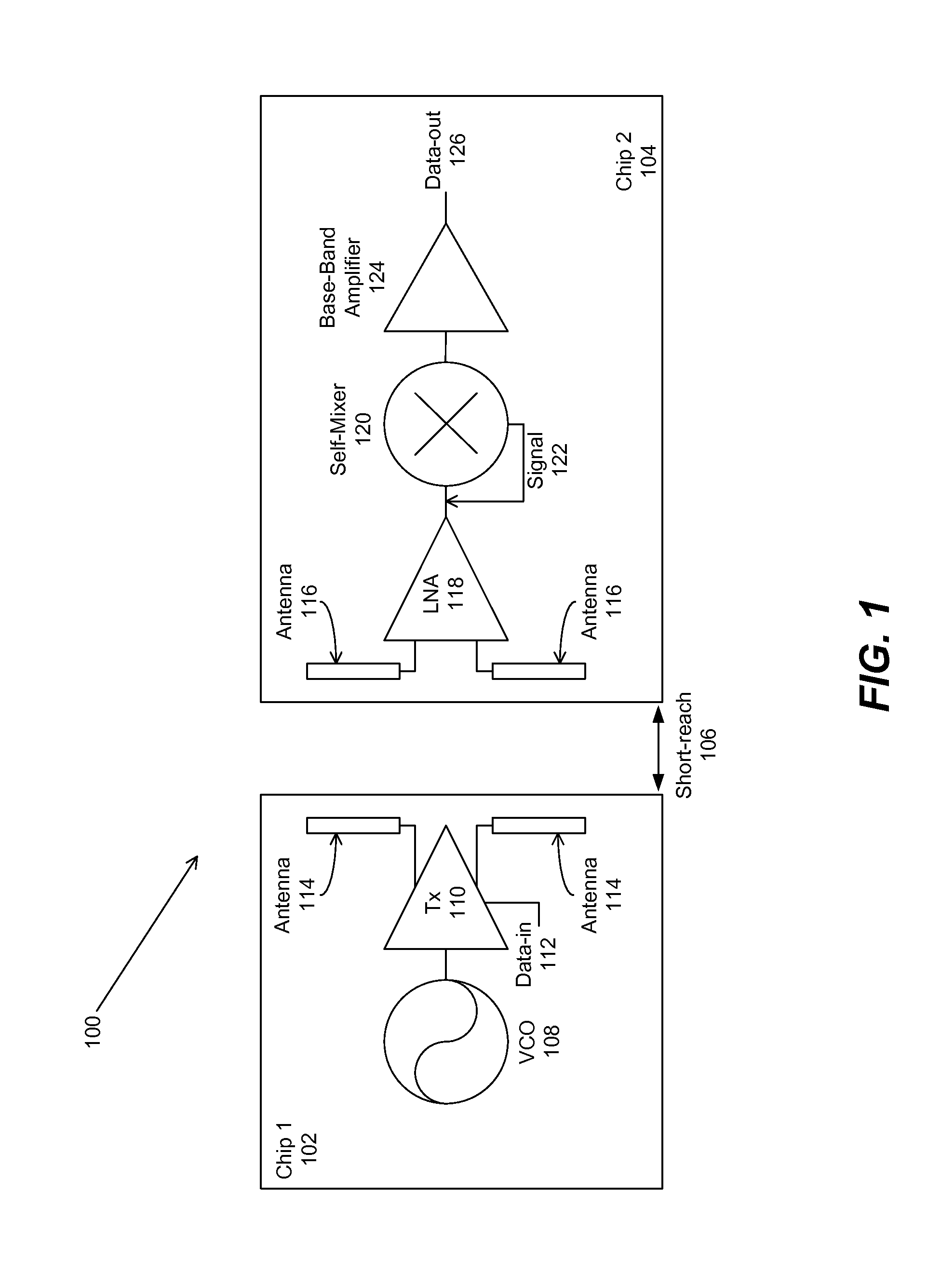
The present invention is about a new type of wireless interconnect called M2W2 that can transmit and receive signals at millimeter-wave frequencies for short-range wireless communication with high data rate capability. It uses asynchronous modulation and differential signaling, with a differential-mutual-mixer as an envelope detector to demodulate the millimeter-wave carrier signal. The interconnect has a transmitter for amplifying and radiating the modulated millimeter-wave carrier signal, a receiver for amplifying and converting the received millimeter-wave carrier signal, and on-chip or bond-wire dipole antennas for signal transmission and reception. The technical effects of this invention are high data rate capability and improved millimeter-wave wireless communication.

Problems solved by technology

On-chip interconnects, especially for multi-processor chips and network-on-a-chip, have been projected as the limiting factor in terms of bandwidth, power and latency.
However, on-chip interconnects remain non-scalable and non-reconfigurable.
However, this on-chip antenna required the use of a phase and frequency synchronous modulation scheme, such as binary phase-shifted-keying (BPSK), which increased the complexity of the architecture and overall power consumption.

Method used


Image

  • Milli-meter-wave-wireless-interconnect (m2w2-interconnect)method for short-range communications with ultra-high data rate capability
  • Milli-meter-wave-wireless-interconnect (m2w2-interconnect)method for short-range communications with ultra-high data rate capability
  • Milli-meter-wave-wireless-interconnect (m2w2-interconnect)method for short-range communications with ultra-high data rate capability

Examples


Embodiment Construction

[0026]In the following description of the preferred embodiment, reference is made to the accompanying drawings which form a part hereof, and in which is shown by way of illustration a specific embodiment in which the invention may be practiced. It is to be understood that other embodiments may be utilized and structural changes may be made without departing from the scope of the present invention.

[0027]Technical Disclosure

[0028]The present invention comprises a wireless interconnect for transmitting and receiving signals at specified frequencies for short-range communication with high data rate capability, comprising the M2W2 interconnect, where the specified frequencies are millimeter-wave frequencies, using an asynchronous modulation scheme and differential signaling architecture. The M2W2 interconnect transmits data wirelessly, in contrast to previous implementations of RF-I (radio frequency interconnects) that utilize a controlled-impedance transmission medium [2]. Moreover, the...


PUM


Abstract

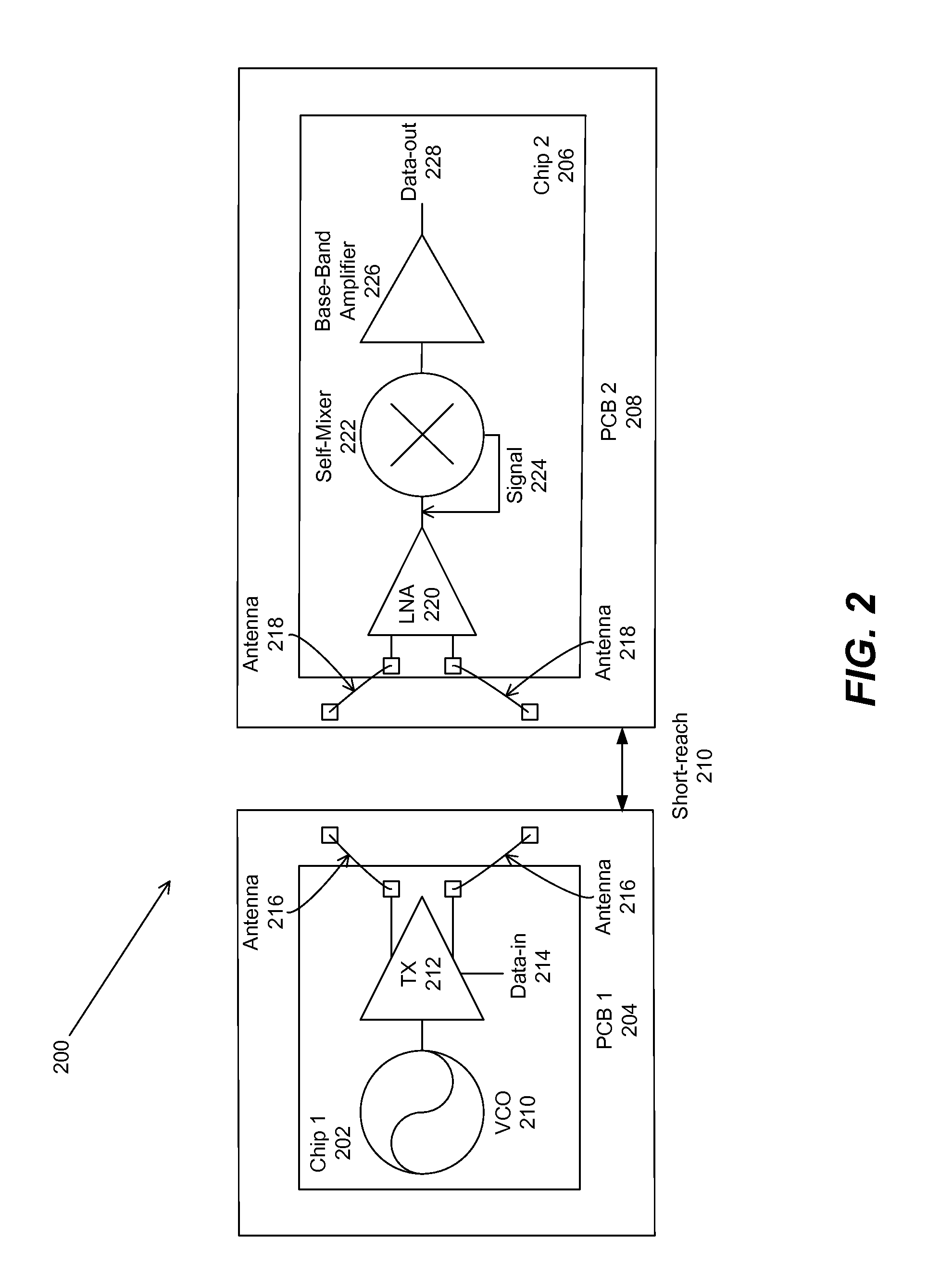
A millimeter wave wireless (M2W2) interconnect is used for transmitting and receiving signals at millimeter-wave frequencies for short-range wireless communication with high data rate capability. The transmitter and receiver antennae may comprise an on-chip differential dipole antenna or a bond-wire differential dipole antenna. The bond wire differential dipole antenna is comprised of a pair of bond wires connecting between a pair of pads on an integrated circuit (IC) die and a pair of floating pads on a printed circuit board (PCB).

Description

CROSS REFERENCE TO RELATED APPLICATIONS[0001]This application is a continuation under 35 U.S.C. Section 120 of co-pending and commonly-assigned:[0002]U.S. Utility patent application Ser. No. 13 / 377,124, filed on Dec. 8, 2011, by Sai-Wang Tam and Mau-Chung F. Chang, entitled “MILLI-METER-WAVE-WIRELESS-INTERCONNECT (M2W2—INTERCONNECT) METHOD FOR SHORT-RANGE COMMUNICATIONS WITH ULTRA-HIGH DATA RATE CAPABILITY,” attorneys' docket number 30435.209-US-WO (2009-445-2), which application claims the benefit under 35 U.S.C. Section 365(c) of co-pending and commonly-assigned:[0003]P.C.T. International Patent Application Serial No. PCT / US2010 / 038033, filed on Jun. 9, 2010, by Sai-Wang Tam and Mau-Chung F. Chang, entitled “MILLI-METER-WAVE-WIRELESS-INTERCONNECT (M2W2—INTERCONNECT) METHOD FOR SHORT-RANGE COMMUNICATIONS WITH ULTRA-HIGH DATA RATE CAPABILITY,” attorneys' docket number 30435.209-US-P1 (2009-445-2), which application claims the benefit under 35 U.S.C. Section 119(e) of co-pending and ...

Claims


Application Information

Patent Timeline
Patent Type & Authority Applications(United States)
IPC IPC(8): H04B5/00H04B5/02
CPCH04B5/02H04B5/0031H01L2224/49171H04B5/72H04B5/48
Inventor TAM, SAI-WANGCHANG, MAU-CHUNG F.
Owner RGT UNIV OF CALIFORNIA
Learn More