Wheel position detector and tire inflation pressure detector having the same

a technology of position detector and tire inflation pressure, which is applied in the direction of pressure difference measurement between multiple valves, instruments, digital computer details, etc., can solve the problem of not being able to specify the wheel position, and achieve the effect of reducing tooth position variation, accurately specifying the wheel position, and shortening the period of tim

Inactive Publication Date: 2014-12-18
DENSO CORP
View PDF8 Cites 3 Cited by
  • Summary
  • Abstract
  • Description
  • Claims
  • Application Information

AI Technical Summary

Benefits of technology

[0014]In the above tire inflation pressure detector, the wheel position detector can accurately find the tooth position at the frame reception timing. Based on the accurate tooth position, the wheel position detector specifies the wheel mounted with the transmitter that transmitted the frame. The wheel position detector can thereby reduce a tooth position variation and accurately specify the wheel position in a shorter period of time.

Problems solved by technology

The method cannot specify the wheel position until the necessary amount of data is acquired.

Method used


Image

  • Wheel position detector and tire inflation pressure detector having the same
  • Wheel position detector and tire inflation pressure detector having the same
  • Wheel position detector and tire inflation pressure detector having the same

Examples


first embodiment

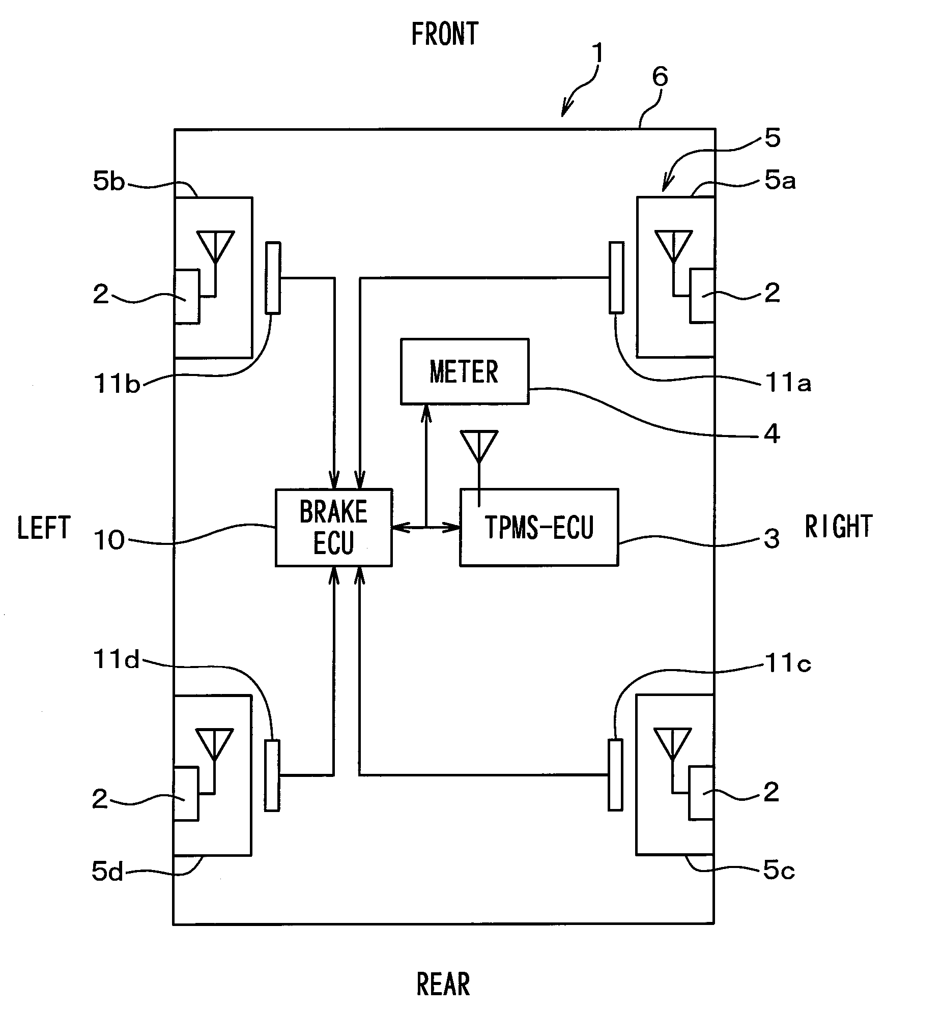
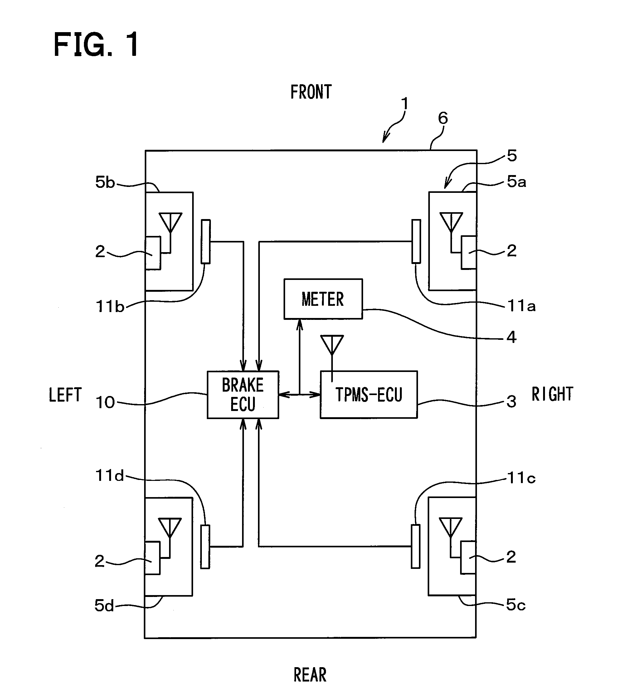
[0024]The first embodiment of the disclosure will be described with reference to the accompanying drawings. FIG. 1 illustrates an overall configuration of a tire inflation pressure detector including a wheel position detector according to the first embodiment of the disclosure. The top of FIG. 1 corresponds to the front of a vehicle 1. The bottom of FIG. 1 corresponds to the rear thereof. The following describes the tire inflation pressure detector according to the embodiment with reference to FIG. 1.

[0025]As illustrated in FIG. 1, the tire inflation pressure detector is attached to the vehicle 1 and includes a transmitter 2, an ECU 3 for the tire inflation pressure detector, and a meter 4. The ECU 3 functions as a receiver and is hereinafter referred to as a TPMS-ECU (Tire Pressure Monitoring System ECU). To specify a wheel position, the wheel position detector uses the transmitter 2 and the TPMS-ECU 3 provided for the tire inflation pressure detector. In addition, the wheel positi...


PUM


Abstract

A wheel position detector for a vehicle includes: a transmitter at each wheel having a first control portion for generating and transmitting a frame with specific identification information; and a receiver at a vehicle body receiving the frame from one wheel and having a second control portion for performing wheel position detection; and a wheel speed sensor for detecting a tooth of a gear. The second control portion: acquires gear information indicating a tooth position; corrects the tooth position based on a time difference between acquiring of the gear information and receiving time of the frame; and specifies the one wheel based on the tooth position at reception time.

Description

CROSS REFERENCE TO RELATED APPLICATION[0001]This application is based on Japanese Patent Application No. 2011-288245 filed on Dec. 28, 2011, the disclosure of which is incorporated herein by reference.TECHNICAL FIELD[0002]The present disclosure relates to a wheel position detector that automatically detects at which position of a vehicle a wheel is mounted. More particularly, the disclosure is favorably applicable to a direct-type tire inflation pressure detector that detects a tire inflation pressure by directly attaching a transmitter having a pressure sensor to a wheel mounted with a tire, allowing the transmitter to transmit a detection result from the pressure sensor, and allowing a receiver attached to the vehicle to receive the result.BACKGROUND ART[0003]There is known a direct-type tire inflation pressure detector according to the related art. This type of tire inflation pressure detector uses a transmitter that is provided with a sensor such as a pressure sensor and is dire...

Claims


Application Information

Patent Timeline
Patent Type & Authority Applications(United States)
IPC IPC(8): B60C23/04G01P3/44G01P15/00
CPCB60C23/0489G01P3/44G01P15/003B60C23/0416
Inventor OKADA, NORIAKIWATABE, NOBUYAMORI, MASASHISEKIZAWA, TAKATOSHI
Owner DENSO CORP
Why Eureka
Try Eureka