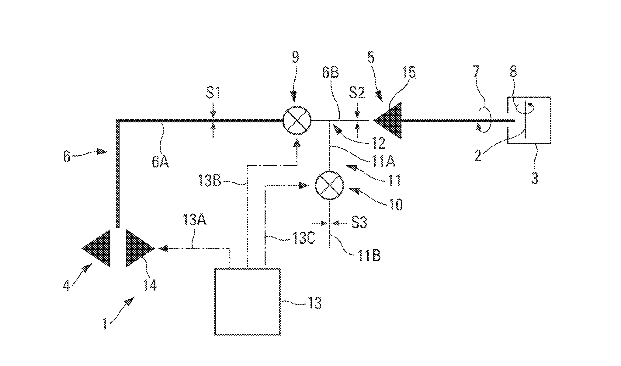
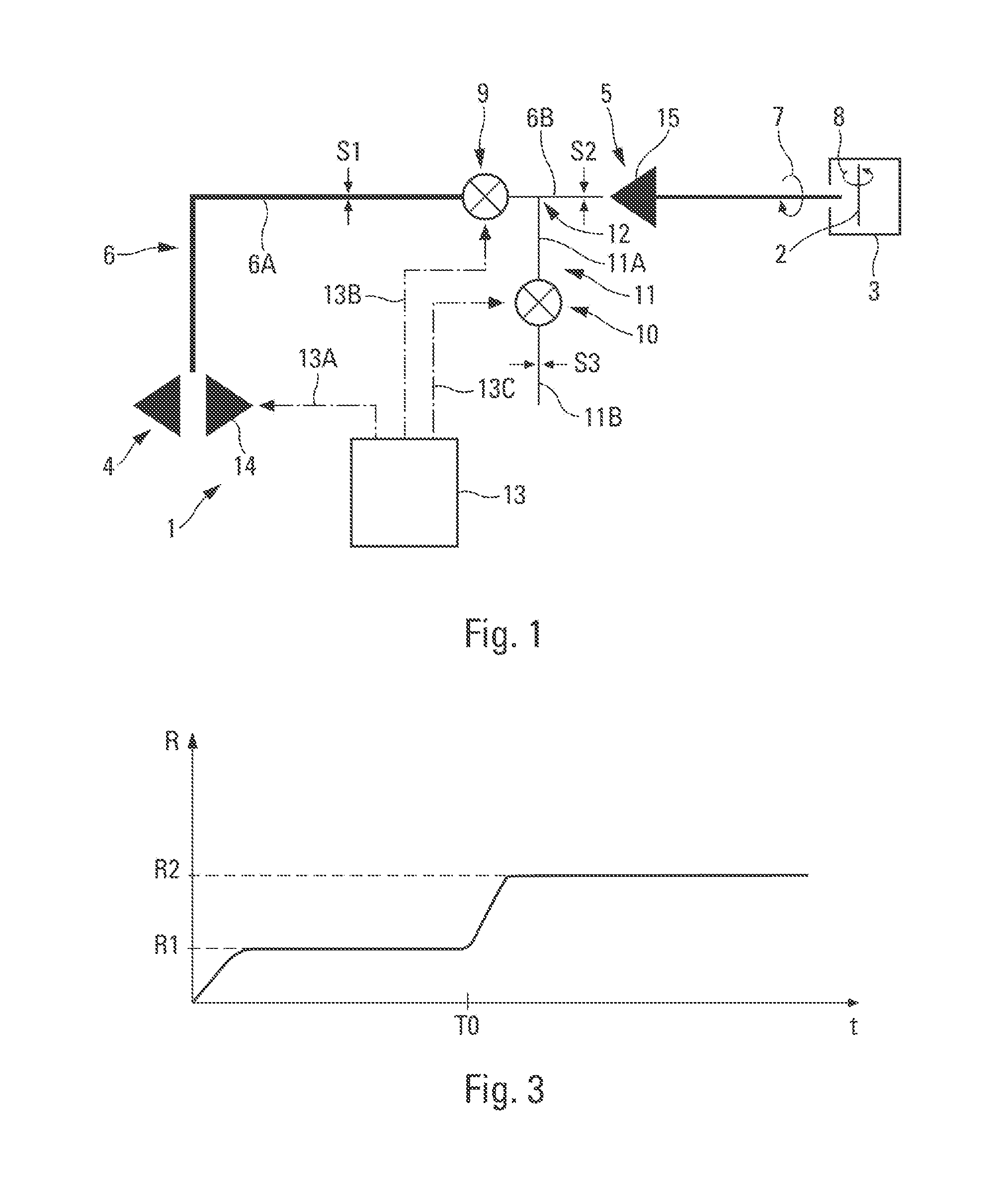
[0042]The system 1 illustrating the invention and depicted schematically in FIG. 1 is intended to spin up a rotary element 2 (a shaft, rotor, etc.) of a mechanical device 3.
[0043]Said system 1 may be applied to any mechanical device 3 a rotary mechanical element 2 of which is to be spun up in an environment subjected to high thermomechanical stresses capable of creating deformations in said rotary element 2, and notably to an aircraft turbomachine
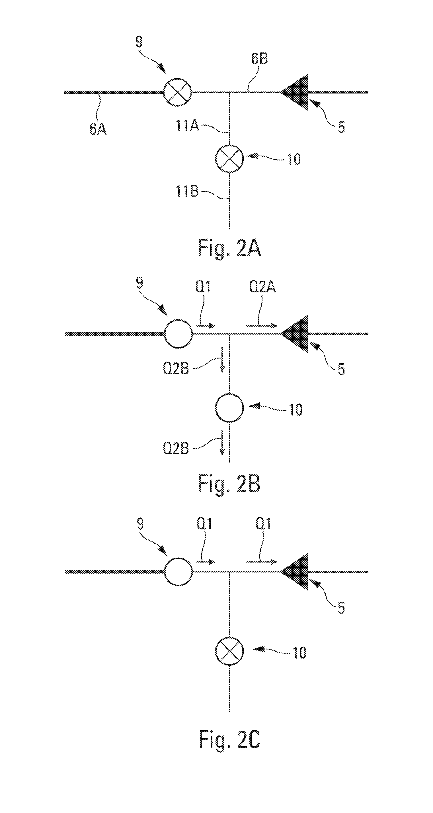
[0044]Said system 1 is of the type comprising: [0045] a conventional fluid generating source 4, for example a pneumatic source or hydraulic source, capable of generating a flow of fluid (air, etc.); [0046] a drive torque generating member 5 connected to the fluid generating source 4 by a pipe 6 referred to as the main pipe capable of transmitting the fluid generated by the fluid generating source 4. Said member 5 is able to produce, when subjected to a flow of fluid, a mechanical force (illustrated by an arrow 7 in FIG. 1) allowing said rotary element 2 of the mechanical device 3 to be spun up as illustrated by an arrow 8; and [0047] a starting valve 9 able to be controlled in such a way as to be able to be brought into one or the other of the following positions: a closed position (indicated by a cross in FIGS. 1 and 2A) and an open position (without a cross).
[0048]The starting valve 9 is arranged on the main pipe 6 between the source 4 and the member 5 so as to create a section of pipe 6A between the source 4 and said starting valve 9 and a section of pipe 6B between said starting valve 9 and said member 5.
[0049]According to the invention, said system 1 additionally comprises a discharge valve 10 able to be controlled in such a way as to be able to be brought into one or the other of the following positions: a closed position (indicated by a cross in FIGS. 1, 2A and 2C) and at least one open position (without a cross). In addition, this discharge valve 10 is arranged on an auxiliary pipe 11 of which a first section 11A is connected to the section of pipe 6B in such a way as to create a fork 12 for the transmission of fluid.
[0050]Said system 1 additionally comprises a control unit 13 which simultaneously controls said fluid generating source 4, said starting valve 9 and said discharge valve 10, as illustrated schematically by the chain line arrows 13A, 13B and 13C respectively.
[0051]Thus, said system 1 comprises a discharge valve 10 which, through being arranged at a fork 12 in the pipe, when open allows some of the fluid generated by the source 4 to be removed via a section 11B of the pipe 11 (preferably into the external environment) so that not all of the fluid is transmitted to the drive torque generating member 5 thus limiting the corresponding rotational speed. Of course, by bringing the discharge valve 10 into its closed position, the system 1 can operate in the usual way, transmitting all of the fluid to said member 5.
[0052]Said system 1 allows a new method of spinning up the rotary element 2 to be performed. When the system 1 is switched off, before being switched on, the two valves 9 and 10 are closed, as depicted in FIG. 2A.
[0053]According to the invention, this method comprises the following successive steps: [0054] a first step (illustrating a prevention mode), in which the starting valve 9 and the discharge valve 10 of the system 1 are both open, as depicted in FIG. 2B, so that only some of the fluid generated by the source 4 and passing through the starting valve 9 (illustrated by an arrow Q1) is transmitted to the member 5. This proportion of fluid is illustrated by an arrow Q2A. The rest of the fluid (illustrated by an arrow Q2B) is removed via the discharge valve 10; and [0055] a second step (illustrating a main mode) that succeeds said first step (or prevention mode), in which said discharge valve 10 is closed and said starting valve 9 remains open, as depicted in FIG. 2C, so that all of the fluid generated by the source 4 is transmitted to said drive torque generating member 5, as illustrated by arrows Q1.
[0056]Thus, at the start of spin up (or startup), during said first step, and for as long as a significant thermal gradient able to generate deformation as specified hereinbelow remains, only some of the fluid generated by the source 4 is transmitted to said member 5 so that the rotational speed is limited.
[0057]The rotational speed R is thus limited to a level R1 as illustrated schematically in FIG. 3 for the length of time T0 of said first step, during which the temperature becomes relatively uniform across the mechanical device 3.
[0058]Said second step, during which all of the fluid is transmitted to said member 5 so that the maximum speed R2 is reached, is performed when the temperature gradient causing the deformation has reduced enough for the deformation to have disappeared.
[0059]During the switchover from prevention mode to the main mode, there is a reduction in the rate of leakage (or discharge) allowing a partial or total progressive increase in the drive torque to the member 5 through the partial or total progressive closure of the discharge valve 10.
[0060]Timing diagrams relating to the abovementioned procedure are depicted in FIG. 4. This FIG. 4 comprises four superposed graphs, defined along the same time abscissa t (comprising successive instants t1 to t7) and successively illustrating, from the top downwards: [0061] the position P1 of the discharge valve 10 between a closed position (F1) and an open position (O1); [0062] the position P2 of the starting valve 9 between a closed position (F2) and an open position (O2); [0063] the situation E1 of the first method step: performance (A1) or absence of performance (B1) of this step; and [0064] the situation E2 of the second method step: performance (A2) or absence of performance (B2) of this step.
[0065]More specifically: [0066] initially, the system 1 is not in operation and the valves 9 and 10 are closed; [0067] at an instant t1,the discharge valve 10 is commanded (by the control unit 13) to open, and is wide open at an instant t2; [0068] at this instant t2, the starting valve 9 is commanded (by the control unit 13) also to open, this instant t2 corresponding to the start of the first step, and it is wide open at an instant t3; [0069] at a later instant t4, the discharge valve 10 is commanded (by the control unit 13) to close, this instant t4 corresponding to the end of the first step or to the start of the second step, and it is fully closed at an instant t5; and [0070] at an instant t6, the starting valve 9 is commanded (by the control unit 13) to close and is completely closed at an instant t7, this instant t7 corresponding to the end of the second step and therefore to the end of the spin-up procedure.
[0071]The opening and closing of the valves 9 and 10 are therefore carried out in a coordinated fashion so as to allow transfers of power according to the functions to be performed: prevention mode or main mode. The discharge valve 10 is operated with a phase lead with respect to the starting valve 9.
[0072]The discharge valve 10 therefore, through suitable control, is able to create a level R1 by setting a maximum flow entering the member 5. The discharge valve 10 is connected to the main pipe 6 by the pipe 11 which has a cross section S3 (leakage cross section) that is variable or fixed. This discharge valve 10 can be produced in various ways and allows the leakage pipe 11 to be opened partially or fully (i.e., progressively or not). To do this, the control unit 13 controls the angle of opening of the discharge valve 10.
[0073]Moreover, in a preferred embodiment, the cross section S1 of the section of pipe 6A (FIG. 1) is greater than the cross section S2 of the section of pipe 6B.
[0074]This feature, which dictates the main supply flow rate, allows the maximum flow rate to be limited (sonic throat or any other throttling device) in the event of breakage (discharge valve) or any other failure of the invention. This cross section, which may be variable or fixed according to the operational conditions, performs functions of protection and of limiting the pneumatic or other power tapped from the source 4 of the system 1.
[0075]The increase in cross section is established according to objectives of limiting power upstream and downstream and is variable or fixed according to operational conditions. In one particular embodiment, the cross section S1 of the section 6A has a diameter falling within a range of values defined between 101% and 115% of the diameter of the cross section S2 of the section 6B.
[0076]In a preferred embodiment, said fluid generating source 4 comprising an air generating source 14 and said drive torque generating member 5 comprises a turbine 15.
[0077]Furthermore, in a specific application to the starting of a turbomachine, said device 3 corresponds to an aircraft turbomachine and the rotary element 2 corresponds to the rotor of this turbomachine The flow of air generated by the source 14, for example an auxiliary power unit or APU, is sent to the turbine 15 via the valve 9 which for example corresponds to a starter valve of the ATS (Air Turbine Starter) type. At output the turbine 15 produces a mechanical force capable of turning the rotor of the engine (turbomachine) in order to start it. The engine is then ignited in the usual way after fuel has been injected into the appropriate parts of the engine which have been set in rotation by the rotor.
[0078]In a simplified embodiment, during the spinning up of the rotary element 2, the control unit 13 switches the system 1 to prevention mode and then, after a predetermined length of time T0, switches it into main mode. By way of illustration, in order to prevent a phenomenon of the “bowed rotor” type, a length of time T0 of the order of 25 to 50 seconds is compatible with the reduction of the corresponding internal thermal gradient (in the rotor bladings and in the internal cavities of the engine).
[0079]Furthermore, in a more evolved embodiment, the prevention mode is performed only if the control unit 13 obtains information indicating that there is a temperature gradient across the rotary element 2, for example in the blading of a turbomachine rotor, or that there is deformation of the rotary element 2 (expansion of the material of the rotary element 2, clearance with respect to the axis of rotation), otherwise operation in prevention mode is prohibited. Such information is obtained when the rotary element 2 is not being driven in rotation, with both valves 9 and 10 closed.
[0080]To do that, the system 1 comprises a monitoring unit 16 which is connected by a link 17 to the control unit 13 as depicted in FIG. 5, and which is configured to monitor at least one parameter able to provide information indicative of a deformation of thermomechanical origin of the rotary element 2 of the mechanical device 3 before it is spun up. Said monitoring unit 16 for that purpose comprises at least one sensor, and preferably a plurality of sensors CA1 to CAN, N being an integer greater than 1.
[0081]By way of illustration, said monitoring unit 16 may, by way of sensors CA1 to CAN, comprise at least some of the following sensors: [0082] one or more temperature sensors sensing the temperature of the device 3 and/or of the outside of the device 2; [0083] a clock for determining the time for which the device 3 is switched off. Beyond a certain length of time (for example beyond 1 h30 in the case of a phenomenon of the aforementioned “bowed rotor” type) the rotary element 2 is considered to be cold and the risk of deformation is considered not to exist; [0084] a clock for determining the operating time of the device 3 according to the power or energy supplied in its previous operation, for example in a previous flight in the case of an aircraft turbomachine; and [0085] one or more displacement transducers to measure radial or axial clearances of the shaft line or lines with respect to the static or rotary structures that are to be protected.
[0086]Because the angle of opening of the discharge valve 10 can be controlled, transition from prevention mode to main mode takes place progressively, under the control of the control unit 13.
[0087]Moreover, in one particular embodiment, the duration or end of the prevention mode may be determined via the control unit 13 on the basis of data gathered from the device 3. These data are compared against a threshold by the control unit 13 and the crossing of this threshold (in one direction or the other depending on the data item being considered) causes the switching over of the system 1 by the control unit 13 into main mode (and therefore the end of the prevention mode). This information is obtained when the rotary element 2 is driven in rotation, with both valves 9 and 10 open.
[0088]To do this, the system 1 comprises a monitoring unit 18 which is connected via a link 19 to the control unit 13 as depicted in FIG. 5 and which is configured to monitor at least one parameter allowing information to be supplied relating to a deformation of thermomechanical origin of said rotary element 2 of the mechanical device 3 during spin up (prevention step).
[0089]Said monitoring unit 18 comprises at least one sensor and preferably a plurality of sensors CB1 to CBP, P being an integer greater than 1.
[0090]In one particular embodiment, said monitoring unit 18 comprises at least one sensor of mechanical vibrations indicative of a deformation.
[0091]Furthermore, by way of illustration, said monitoring unit 18 may also comprise, by way of sensors CB1 to CBP, at least some of the following sensors: [0092] one or more sensors sensing temperature inside the device 3, whatever the location (compressors, bearings, cavities, gas outlet, etc.); [0093] one or more sensors sensing temperature of fluids of the device 3 (oil, fuel in particular); [0094] one or more sensors sensing internal or external temperatures of static parts of the device 3; [0095] one or more sensors of rotational speed of shafts and/or rotary parts of the device 3; [0096] one or more displacement transducers to measure radial or axial clearances of the shaft line or lines with respect to the static or rotary structures that are to be protected; [0097] one or more load sensors for measuring the movements of bearings or structures; [0098] one or more (static and/or total) pressure sensors and temperature sensors measuring pressure or temperature in the supply (measuring entropy, supply flow rate, etc.); [0099] one or more (static and/or total) pressure and temperature sensors in the discharge (measuring entropy, supply flow rate, etc.); and [0100] one or more (static and/or total) pressure and temperature sensors measuring at the supply to the member 5 (measuring entropy, supply flow rate, etc.).
[0101]Furthermore, in one particular embodiment, the rate of flow of fluid (air) discharged during the prevention mode is determined by the control unit 13 on the basis of data gathered from the device 3. Thus, before the control unit 13 switches the system 1 over to main mode (and therefore before the end of the prevention mode), the discharge valve 10 (the angle of opening of which can be controlled) is controlled on the basis of the data received by the sensors, with a view to modulating the rotational speed of the rotary element 2 in order not to damage said rotary element 2 and/or said mechanical device 3. In this particular embodiment, the prevention mode therefore involves active regulation of the rotational speed of the rotary element 2, which regulation is obtained by modulating the openness of the discharge valve 10, i.e., by actively regulating the flow rate.
[0102]As is apparent from the foregoing specification, the invention is susceptible of being embodied with various alterations and modifications which may differ particularly from those that have been described in the preceding specification and description. It should be understood that I wish to embody within the scope of the patent warranted hereon all such modifications as reasonably and properly come within the scope of my contribution to the art.