Speed control system for wheeled hydraulic traveling vehicle

Inactive Publication Date: 2005-09-06
HITACHI CONSTR MASCH CO LTD
View PDF20 Cites 32 Cited by
  • Summary
  • Abstract
  • Description
  • Claims
  • Application Information

AI Technical Summary

Benefits of technology

[0015]As described above, if an ultra low speed travel signal is issued, the displacement amount of the hydraulic motor is set to the maximum and amount of the pressure oil supplied from the hydraulic pump to the hydraulic motor is restricted. Furthermore, an upper limit for rotational speed of the prime mover is set low. In this manner, it is possible to significantly reduce

Problems solved by technology

The ultra low travel speed is achieved by switching the transmission to a low-speed range and adjusting the amount

Method used


Image

  • Speed control system for wheeled hydraulic traveling vehicle
  • Speed control system for wheeled hydraulic traveling vehicle
  • Speed control system for wheeled hydraulic traveling vehicle

Examples


Example

[0023]The case of applying a speed control system for a wheeled hydraulic traveling vehicle of the present invention to a wheeled hydraulic excavator will now be described using FIG. 1 to FIG. 7. A wheeled hydraulic excavator comprises an undercarriage, an upper structure connected on the undercarriage so as to be capable of swinging, and an attachment for working attached to the upper structure.

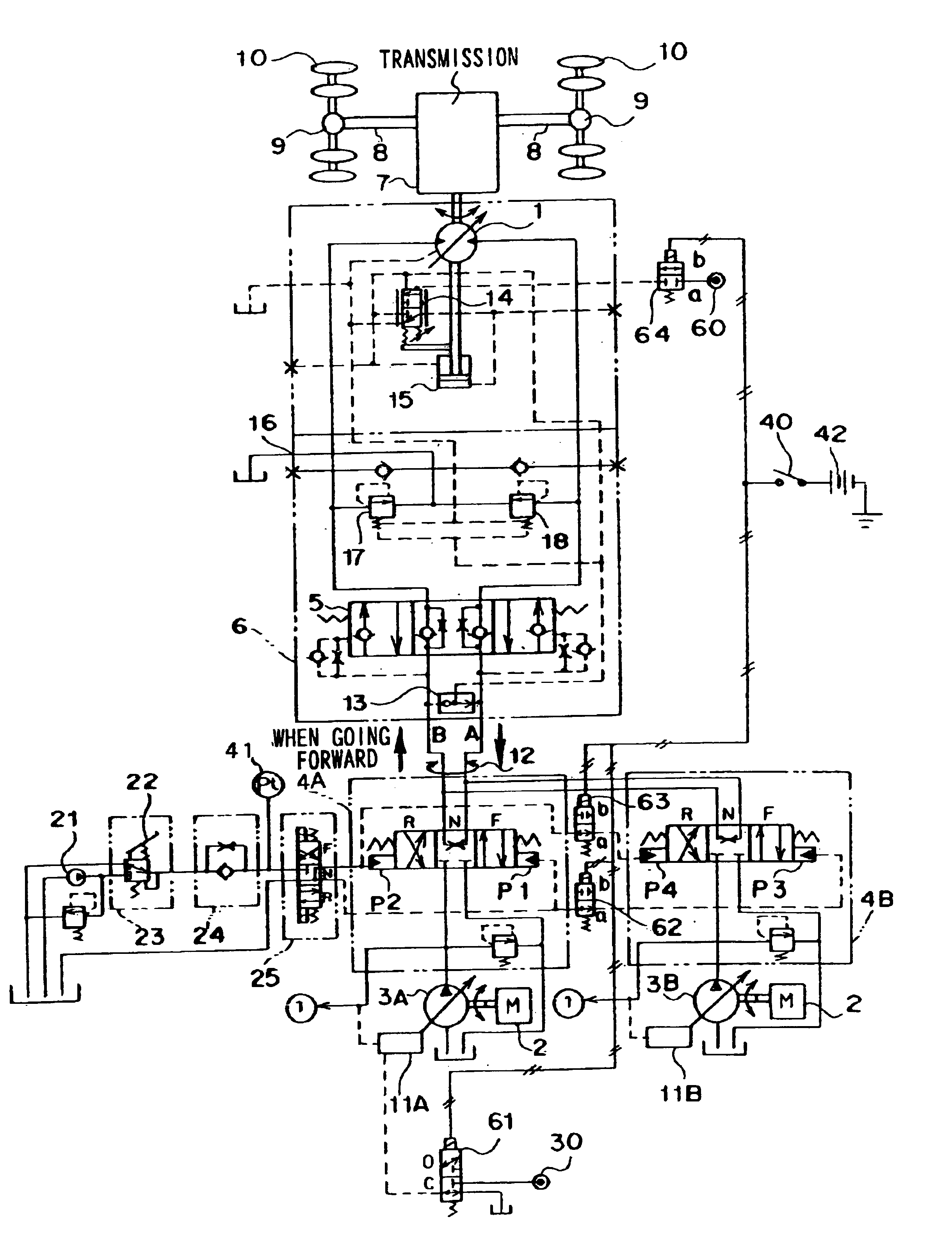
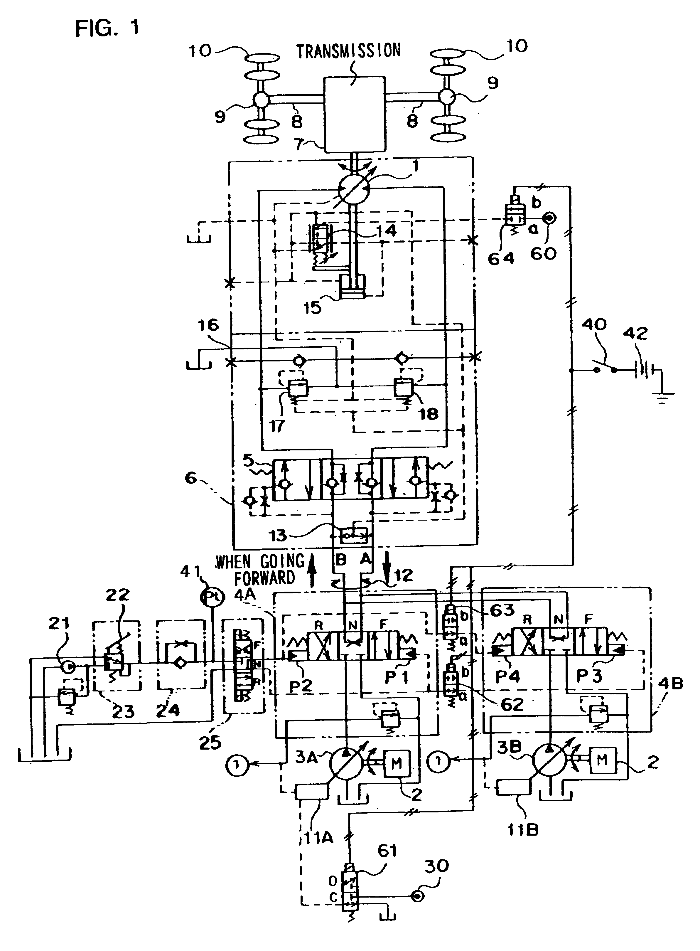
[0024]FIG. 1 is a hydraulic circuit diagram for traveling of the wheeled hydraulic excavator. As shown in FIG. 1, the travel hydraulic circuit of the wheeled hydraulic excavator comprises a pair of variable displacement main pumps 3A and 3B respectively driven by an engine (prime mover) 2, a pair of control valves 4A and 4B provided respectively corresponding to the main pumps 3A and 3B, a brake valve 6 with a counter balance valve 5 built therein, and a variable displacement hydraulic motor for traveling 1. The control valves 4A and 4B are driven by a pilot pressure from a pilot control cir...


PUM


Abstract

Control valves are respectively provided in a pair of variable displacement hydraulic pumps. If an ultra low speed travel signal is issued in response to an ultra-low-speed switch turned on, one of the control valves is fixed to a neutral position by a solenoid valve. And a displacement amount of a travel motor is fixed at a maximum displacement by another solenoid valve. In this way, an upper limit for motor rotation speed is significantly reduced. As a result, it is possible to realize the ultra low speed travel with maximum operation of an accelerator pedal, without the need for subtle operation of the accelerator pedal.

Description

[0001]The present application is based on Japanese patent application No. 2000-273736 (filed Sep. 8, 2000), the contents thereof are incorporated herein by reference.TECHINICAL FIELD[0002]The present invention relates to a speed control system for a wheeled hydraulic traveling vehicle such as a wheeled hydraulic excavator.BACKGROUND ART[0003]Generally, a traveling control circuit of a wheeled hydraulic excavator comprises a variable displacement hydraulic pump driven by a prime mover, a variable displacement hydraulic motor driven by pressure oil discharged from the hydraulic pump, and a control valve for controlling flow of pressure oil fluid supplied from the hydraulic pump to the hydraulic motor. A pair of hydraulic pumps and a pair of control valves are provided. Respective control valves are simultaneously switched to merge pressure oil from each hydraulic pump and supply this merged oil to the hydraulic motor.[0004]The motor rotation speed of this type of wheeled hydraulic exc...

Claims


Application Information

Patent Timeline
IPC IPC(8): F16H61/40F16H61/44B60K17/10F16H59/44B60W10/06F02D29/04F16H61/42F16H61/423F16H61/431F16H61/433F16H61/444F16H61/46F16H61/47
CPCB60W10/06B60W30/18063F16H61/423F16H61/431F16H61/433F16H61/444F16H61/47B60K5/08B60K2741/16B60W2710/0644B60W10/04B60W10/103
Inventor ISHIMARU, HIDEHARUSHINYA, TOSHIHIKO
Owner HITACHI CONSTR MASCH CO LTD
Why Eureka
Try Eureka