Attachable pad for a supporter

Inactive Publication Date: 2014-12-25
PARK MIN SIK
View PDF3 Cites 19 Cited by
  • Summary
  • Abstract
  • Description
  • Claims
  • Application Information

AI Technical Summary

Benefits of technology

[0015]As described above, the configuration including the body wing 480 and the second pressing member 490 realizes significant effects that enable a load of 20 kg or more, which cannot be realized in the related art, to be semi-permanently attached using a unique adhesive force, which is referred to as the sealing attachment of the attachment sheet 420. In particular, in the sealing attachment configuration of the invention, the annular packing is provided in the attachment sheet contact portion on the circumference of the cap, which required essential components in the related art, and the auxiliary attachment configuration that provides a plurality of pieces of plastic packing between the attachment sheet and the surface of the object on which the attachable pad is to be attached is omitted.
[0016]In the invention, after the attachment sheet is tightly attached on the su

Problems solved by technology

However, in the absorber using the difference between the vacuum pressure, which is created inside the absorber, and the ambient atmospheric pressure, there are drawbacks, namely, that

Method used


Image

  • Attachable pad for a supporter
  • Attachable pad for a supporter
  • Attachable pad for a supporter

Examples


Embodiment Construction

[0042]Hereinafter, the present invention will be described in detail with reference to the accompanying drawings.

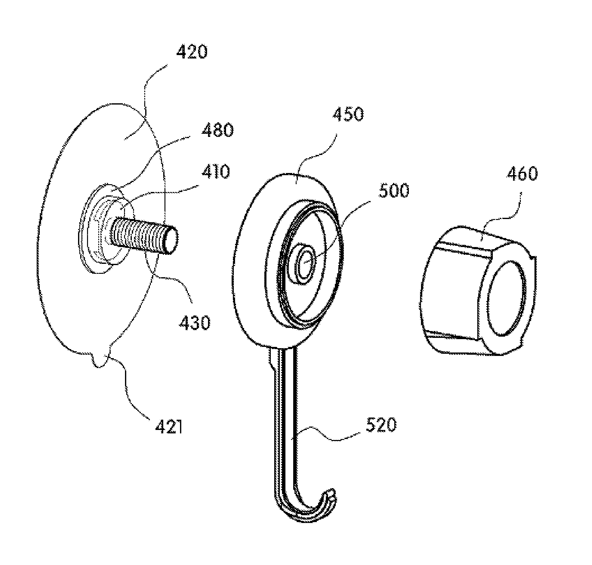
[0043]FIG. 4A is an exploded perspective view of an attachable pad according to an embodiment of the invention, and FIG. 4B is an explanatory view showing the state in which a fixing screw nut 440 and a fixing screw bolt 430 in the view of FIG. 4A are detached. In addition, FIG. 5A is a view showing the state in which the attachable pad in the exploded perspective view of FIG. 4 is assembled and attached to an object wall.

[0044]As shown in FIG. 4A, the basic configuration of the attachable pad of the invention includes an attachable pad body 410; an attachment sheet 420; the fixing screw bolt 430, which can be integrally formed with the body (e.g. by molding), or the fixing screw bolt 430, the length and size of which can be determined depending on the size and weight of an article which is to be supported on the fixing screw nut 440 via the attachable pad, and to the sur...


PUM


Abstract

An attachable pad for a support includes an attachable pad body, an attachment sheet bonded to the attachable pad body, a cap covering the attachable pad body, an operation cap fixing the cap to the attachable pad body, and a support-connecting fixing ring between the cap and the operation cap. A main body wing is integrally provided in the attachable pad body between the attachment sheet and the attachable pad body. A fixing screw nut is integrally molded to the attachable pad body. A fixing screw bolt is separated from the nut to fix the fixing screw bolt to the fixing screw nut. A second pressing member is provided inside the cap to support the body wing. The second pressing member presses the body wing together with the body to the surface of an object while a first pressing member is pressing the body to the surface of the object.

Description

CROSS REFERENCE TO RELATED APPLICATIONS[0001]This is a continuation-in-part application of U.S. patent application Ser. No. 13 / 522,086, filed on Jul. 13, 2012, which is a national entry of International Application No. PCT / KR2010 / 007496, filed on Oct. 29, 2010, which claims a priority to and the benefit of Korean Patent Application No. 10-2010-0105811, filed on Oct. 28, 2010, the contents of which in their entirety are herein incorporated by reference.TECHNICAL FIELD[0002]The present invention relates to an attachable pad, and more particularly, to an attachable pad that can overcome the drawbacks of an attachable pad of the related art, namely, that the supportable load is tightly limited when vacuum compression is used or that the sealing attachment is disabled as time passes or vacuum pressure is released when the attachable pad is based on a sealing attachment. The attachable pad can maintain the bonding of the sealing attachment as time passes, and thus semi-permanently maintai...

Claims


Application Information

Patent Timeline
IPC IPC(8): F16B47/00A47G1/17
CPCA47G1/17F16B47/00
Inventor PARK, MIN SIK
Owner PARK MIN SIK
Why Eureka
Try Eureka