

Imaging lens
a technology of image sensor and lens, applied in the field of image sensor, can solve the problems of inability to meet the demand satisfactorily, inability to achieve the same level of high optical performance as in a small image sensor, and inability to deliver satisfactory optical performance, etc., to achieve the effect of wide field of view and high optical performan
- Summary
- Abstract
- Description
- Claims
- Application Information
AI Technical Summary
Benefits of technology
Problems solved by technology
Method used
Image

Examples
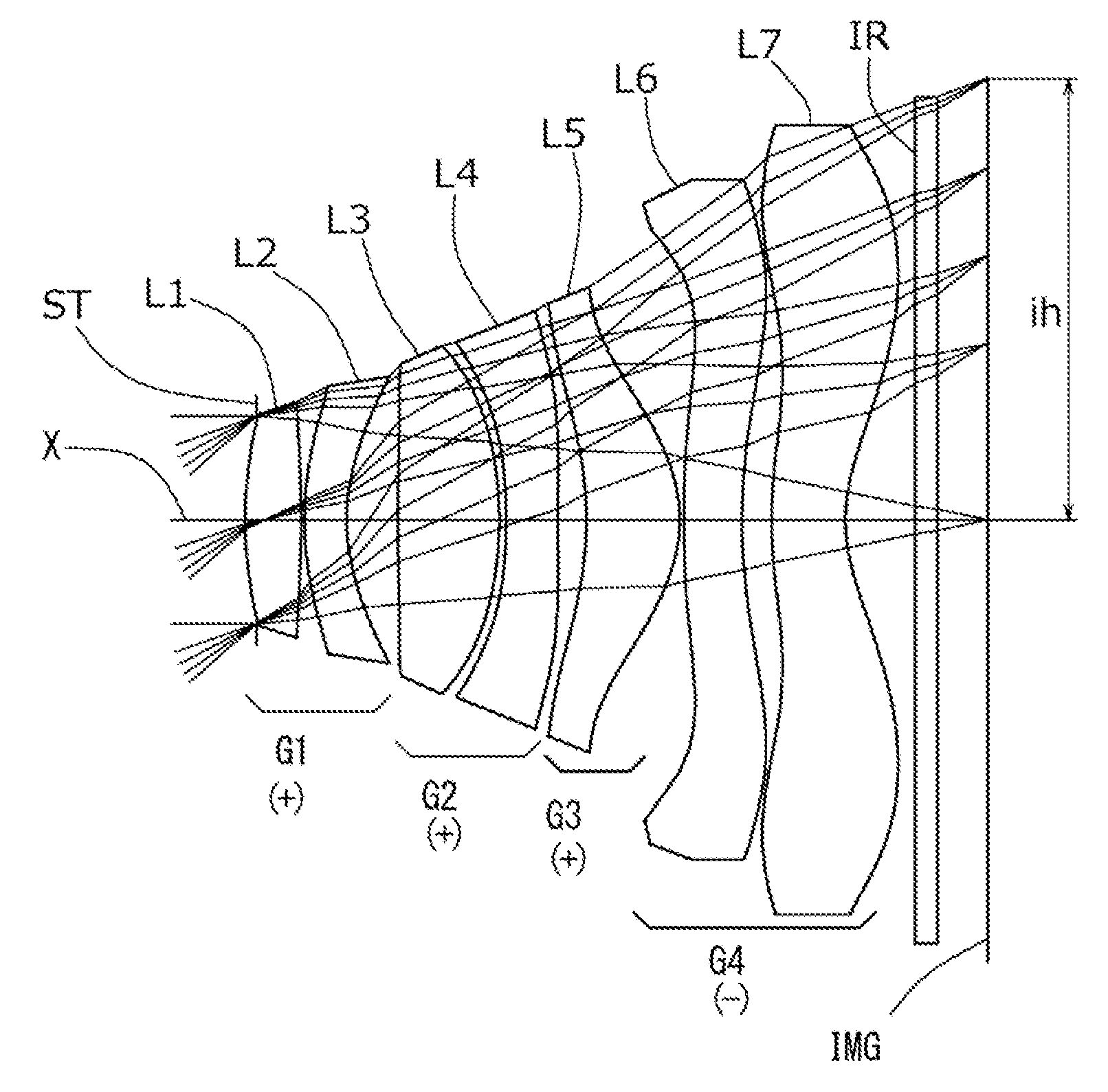
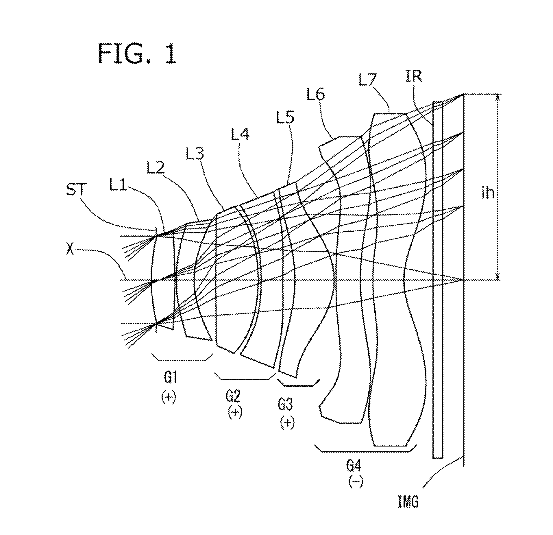
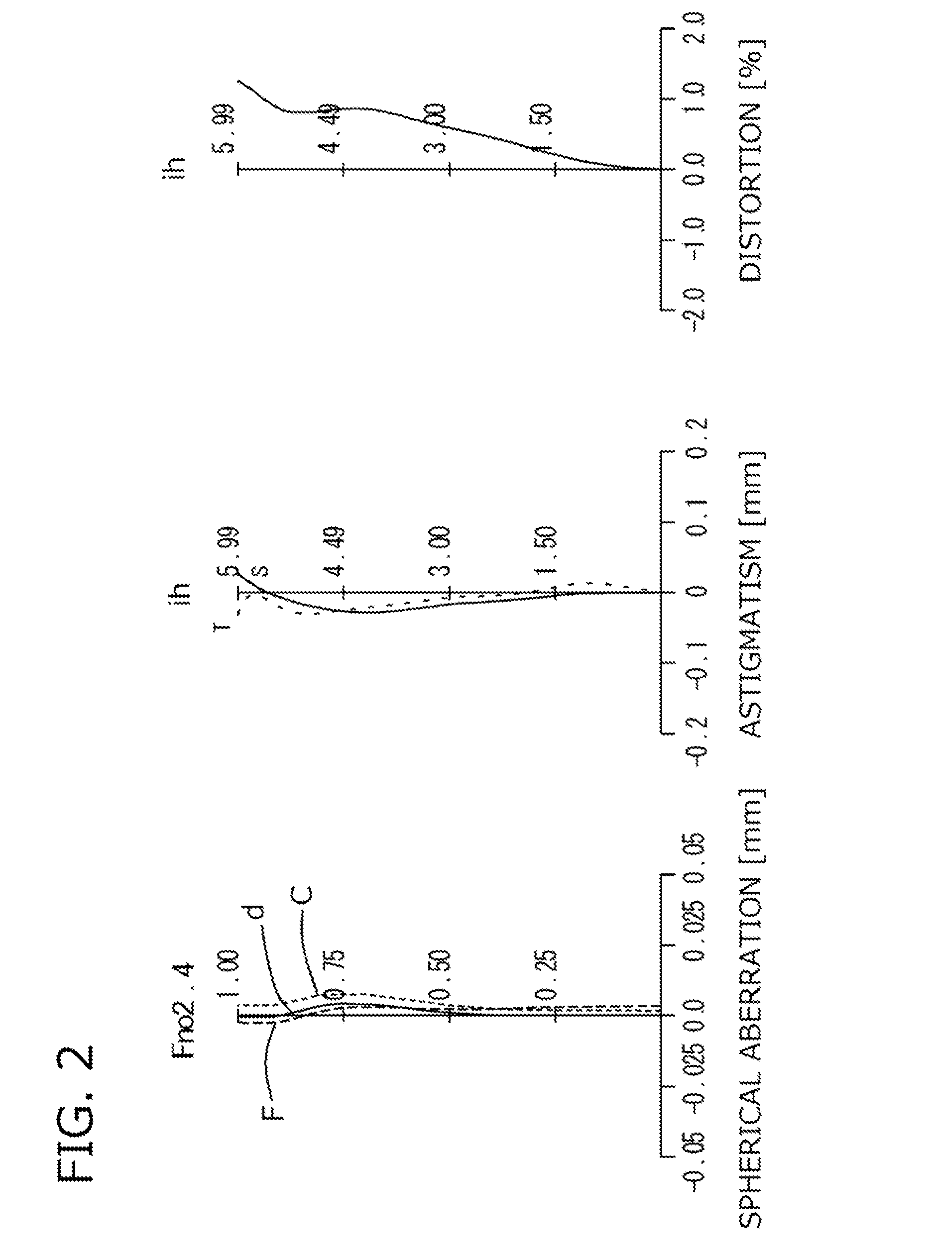
example 1
[0132]The basic lens data of Example 1 is shown below in Table 1.
TABLE 1Example 1in mmf = 6.76Fno = 2.40ω(°) = 41.2ih = 5.99TTL = 9.97Surface DataCurvatureSurfaceRefractiveAbbeSurface No. iRadius rDistance dIndex NdNumber vd(Object Surface)InfinityInfinity 1 (Stop)Infinity−0.15 2*5.9020.7601.543855.57 3*13.3780.040 4*4.1960.5761.614225.58 5*2.6570.692 6*28.4681.3811.543855.57 7*−5.0000.093 8*−7.7630.7001.614225.58 9*36.6560.38910*−4.7751.2701.534656.1611*−1.9760.05312*14.5030.7901.614225.5813*7.7850.40214*6.11471.0001.534656.1615*2.17310.80016Infinity0.3001.564051.3017Infinity0.834Image PlaneInfinityConstituent Lens DataLensStart SurfaceFocal Length127.6424−13.74367.9448−10.375105.45612−28.64714−6.92LensComposite Focal LengthThird Lens-Fourth Lens30.08Sixth Lens-Seventh Lens−5.43Aspheric Surface Data2nd Surface3rd Surface4th Surface5th Surface6th Surface7th Surface8th Surfacek0.000E+000.000E+000.000E+000.000E+000.000E+000.000E+000.000E+00A44.733E−047.844E−03−1.319E−02 −2.924E−02 −2....
example 2
[0136]The basic lens data of Example 2 is shown below in Table 2.
TABLE 2Example 2in mmf = 6.76Fno = 2.40ω(°) = 41.2ih = 5.99TTL = 9.57Surface DataCurvatureSurfaceRefractiveAbbeSurface No. iRadius rDistance dIndex NdNumber vd(Object Surface)InfinityInfinity 1 (Stop)Infinity−0.185 2*4.5940.8231.543855.57 3*−16.3730.040 4*5.4080.5001.614225.58 5*3.1850.681 6*−96.7941.0701.534656.16 7*−5.0000.050 8*−13.7590.7001.614225.58 9*25.8440.40210*−3.4821.1701.534656.1611*−1.9550.05312*9.1530.7901.614225.5813*5.0350.55814*5.9221.0551.534656.1615*2.4480.70016Infinity0.3001.564051.3017Infinity0.786Image PlaneInfinityConstituent Lens DataLensStart SurfaceFocal Length126.6924−13.80369.8248−14.525106.58612−19.65714−8.73LensComposite Focal LengthThird Lens-Fourth Lens29.34Sixth Lens-Seventh Lens−5.79Aspheric Surface Data2nd Surface3rd Surface4th Surface5th Surface6th Surface7th Surface8th Surfacek0.000E+000.000E+000.000E+000.000E+000.000E+000.000E+000.000E+00A4−5.727E−04 5.079E−03−1.136E−02 −2.352E−02 ...
example 3
[0141]
TABLE 3Example 3in mmf = 6.78Fno = 2.41ω(°) = 41.1ih = 5.99TTL = 9.29Surface DataCurvatureSurfaceRefractiveAbbeSurface No. iRadius rDistance dIndex NdNumber vd(Object Surface)InfinityInfinity 1 (Stop)Infinity−0.13 2*5.0190.7741.543855.57 3*−6.7450.068 4*8.5490.5321.634923.97 5*3.0690.700 6*286.5570.8861.534656.16 7*−8.4030.053 8*7.1170.6001.634923.97 9*5.6140.65110*−3.9691.0971.534656.1611*−1.9060.05312*11.7110.6701.634923.9713*4.9960.52914*6.22871.0421.534656.1615*2.44790.80016Infinity0.3001.564051.3017Infinity0.641Image PlaneInfinityConstituent Lens DataLensStart SurfaceFocal Length125.4224−7.833615.2948−49.565105.79612−14.27714−8.34LensComposite Focal LengthThird Lens-Fourth Lens20.81Sixth Lens-Seventh Lens−4.95Aspheric Surface Data2nd Surface3rd Surface4th Surface5th Surface6th Surface7th Surface8th Surfacek0.000E+000.000E+000.000E+000.000E+000.000E+000.000E+000.000E+00A4−7.763E−03 6.959E−03−3.606E−03 −2.401E−02 1.186E−038.779E−03−1.347E−02 A6−3.872E−03 −5.264E−03 5.475E−0...
PUM
 Abstract
Description
Claims
Application Information